Quantcast
Channel: LEKULE
Viewing all 1099 articles
Browse latest View live

What Russia's Vostok-18 Exercise with China Means

$
0
0

Moscow knows what it is doing and Washington should take note.

The West got a fresh jolt from Moscow last week. That’s when Russian defense minister Sergey Shoygu announced that Russian armed forces would hold a military exercise in September, called “Vostok-18” [East-18], on a scale not seen since the early 1980s. If there was any doubt that Russia sees itself in a “New Cold War,” Shoygu’s direct reference to the massive “Zapad” [West] exercise from 1981 seems to confirm that is the prevailing mentality in the Kremlin. In fact, Shoygu claimed , “They (the exercises ‘Vostok-2018’) will in some ways recall ‘Zapad-81,’ but in other ways, actually, will be even larger in scale [Они (учения ‘Восток-2018’) в чём-то повторяют ‘Запад-81’, но в чем-то, пожалуй, ещё масштабнее].”

In the same statement, Shoygu declared that the exercise would involve more than one thousand aircraft, almost three hundred thousand soldiers, and nearly all Russian military installations in the Central and Eastern military regions, including also the Northern and Pacific fleets. In the article cited above, moreover, the Russian defense minister is said to have asked gathered journalists to imagine “when 36,000 pieces of equipment including tanks, armored personnel carriers, etc. are simultaneously on the march [когда одновременно на марше находятся примерно 36 тыс. единиц техники, включая танки, БТР, БМП].”

A couple of days later and on the occasion of a visit by a senior Chinese military delegation, Shoygu offered that the relationship between Moscow and Beijing reached “ an unprecedented high level .” Interestingly on that latter occasion, he discussed the participation of Chinese units together with Russian units in the Shanghai Cooperation Organization’s (SCO) anti-terrorism exercises that just took place in Chelyabinsk Oblast, but did not seem to mention the planned cooperation for Vostok-18. And so it does seem that Russia-China military cooperation has genuinely been regularized, with one exercise or exchange following closely upon the next and reaching higher and higher levels of intensity and scope.

Other than the vast scale of the exercise, the fact that Chinese forces have a role seems to have dominated reporting on Vostok-18. But, at least two critical analytical points seem to have been missed. First, the location of the exercise no doubt reflects the Kremlin’s desire to cool down tensions in the European theater. At a time of emerging fissures within the Trans-Atlantic Community, such an enormous exercise close to NATO countries would be excessively provocative and counter to Russia’s interests. That the Kremlin understands this is no doubt a good thing for European security. The other important point that has not registered in most Western analyses is the confluence of the September Eastern Economic Forum in Vladivostok and the Vostok-18 exercise. It’s easy to forget that six months ago, it looked more than a little likely that a massive war would engulf Northeast Asia. The exercise was most likely put together as a show of force meant to favorably impact diplomacy and the related “correlation of forces” in and around the Korean Peninsula.

Undoubtedly, it is also true that Russia-China strategic cooperation has reached a new stage. As an example of new energy and synergy in their bilateral relationship, Moscow has likely been impressed by Beijing’s willingness to explicitly support the new concept of a “Polar Silk Road”—as a critical part of the larger Belt and Road initiative. For instance, China’s announcement that it will build a nuclear icebreaker ( with likely Russian assistance ) can be viewed as a rather serious commitment to the smooth operation of the revitalized Northern Sea Route (NSR). Indeed, Chinese investment is likely to play a crucial role in activating Russia’s long-held dream of a dynamic maritime corridor that traces along its northern coast, bringing some amount of both prestige and prosperity.
 

Yet as good as this sounds, it is fair to say that not all Russians are so optimistic, and some have even suggested that Vostok-18 has a double message that is also meant t o warn Beijing. I have recently described in this forum at least one prolific Russian strategist who considers China as the preeminent threat to Russian national security. Indeed, the Russian media seemed to be registering some disquiet last week over the possible setup of a Chinese military base (or training facility) in eastern Afghanistan. Moreover, one analysis concluded that Beijing might station over five hundred soldiers at that facility, but also assessed that the main purpose was to combat terrorism and also soberly concluded that “the Chinese are acting with extreme caution…[китайцы действуют крайне осторожно].”

Oddly, the Chinese may be talking more about Vostok-18 than the Russians, at least so far. A recent discussion in Global Times [环球时报], for example, crowed that 3,200 Chinese soldiers would participate and the contingent would also bring thirty aircraft as well. The article discusses this new development as a partial break with the past, in which Russia-China exercises were previously small-scale [规模比较小]. But it also notes that Vostok-18 is not a joint exercise [联合军演], but rather Chinese participation in a large-scale Russian exercise. The authors note that Western observers tend to have two contrasting interpretations of Russia-China relations: either as dysfunctional or, at the other end of the spectrum, as an already existing alliance. This article suggests both interpretations are off the mark. They emphatically reject the idea of a Russia-China military alliance, noting that it would represent “such a huge blow against global stability [那对全球稳定将带来多么巨大的冲击].” On reflection, this seems to be a rather mature view of multi-polarity and provide some ample food for thought to Western readers. That might be the point, of course.

Turning back to the Kremlin’s motives, a logical reason why the Russian press is comparatively quiet about Vostok-18 could be that the guns and butter debate in Russia is becoming ever more acute. Against the background of significant protests on the sensitive issue of pension reform, the Kremlin may be a little less eager to flex its military muscles. Yet, this attribute seems to be hard-wired into the Russian DNA. As I absorbed Alexander Solzhenitsyn’s masterly August 1914 , a title I found in an obscure second-hand bookstore over the summer, I found it helps give readers some additional historical perspective regarding Russian leaders’ obsession with rooting out military incompetence. How would history have turned out differently if the Czar’s armies had not suffered catastrophic defeat at Tannenberg? Of course, that defeat followed hard upon grave military failures in the disastrous war against Japan.

Would there have ever been a Bolshevik revolution without these military failures a century ago? Perhaps the Russians can be forgiven for exercising the troops.

And what about the vexing Korean problem that has seen very significant backsliding over the last weeks and yet may form the most potent explanation for the creation of this iteration of Vostok-18? There was a possibility not long ago that Kim Jong-un and Moon Jae-in would actually both attend the Eastern Economic Forum in Vladivostok in September. With Xi Jinping and Shinzo Abe also likely in attendance, that could have been a peace-making opportunity of epochal proportions. 

 Too bad, it seems that both Kim and Moon have most likely opted to pass up this opportunity to hold another inter-Korean summit. While that is also of great importance, it still looks regrettably that all sides have failed to recognize the vital role of personal diplomacy in the emerging multi-polar world, of cross-cutting cleavages, and yet also the imperative to develop solutions that actually conform to existing balances of power. To state the obvious, all the leaders of North East Asia should gather urgently and regularly to try to iron out differences on the most pressing problems, especially denuclearization.

For American negotiators, there must be a realization that neither polite words, nor symbolic (and worthless) gestures, are adequate to accomplish the arduous task at hand . For now, at least, the need for continued forward progress on the vital North Korea issue should form the very highest priority in U.S.-China relations and also actually in U.S.-Russia relations as well.

Lyle J. Goldstein is research professor in the China Maritime Studies Institute at the United States Naval War College in Newport, RI. In addition to Chinese, he also speaks Russian and he is also an affiliate of the new Russia Maritime Studies Institute at Naval War College. You can reach him at goldstel@usnwc.edu. The opinions in his columns are entirely his own and do not reflect the official assessments of the U.S. Navy or any other agency of the U.S. government.


Image: A Russian serviceman walks past the Buk-1M missile system at the Army-2015 international military forum in Kubinka, outside Moscow, Russia, June 16, 2015. REUTERS/Maxim Shemetov 

Chairman Michael McCaul: Empower our Allies to Fight Terrorism in Africa

$
0
0

Terrorism anywhere is a threat to civilization everywhere.

Before September 11, 2001, very few people were concerned with what was happening inside Afghanistan. How could the internal dynamics of a poor country over seven thousand miles away have a direct impact on our lives? That question was answered when Al Qaeda struck our homeland and killed almost three thousand innocent people. In complete shock we wondered, “How could this happen?”

In the aftermath, it was clear that we needed to change our thinking toward weak states on the other side of the world. We could no longer allow them to become safe havens for international terrorists to plot and plan attacks.

In the last seventeen years, we have organized broad coalitions to fight terror groups and prevent future attacks from occurring. We captured 9/11 mastermind Khalid Sheik Mohammed and killed Osama Bin Laden and Abu Musab al-Zarqawi, among others.

More recently, we have been successful on the battlefield against ISIS. After establishing a so-called “caliphate” in Iraq and Syria, American-led forces have retaken much of the land once controlled by ISIS and forced them to splinter their operations.

Many of their fighters have escaped and are regrouping in Africa. They are looking to join other like-minded extremists who share the same goal: to establish a global community that adheres to their flawed interpretation of Islam, wreak havoc on local populations, and attack the West.
 

Today, it is estimated that ten thousand ISIS and Al Qaeda jihadists have already set up camp across the continent. This is in addition to Boko Haram, Al Shabab, and other extremist groups that have been fomenting violence and spreading terror for many years. 

In early August, we commemorated the twentieth anniversary of the bombings of American embassies in Kenya and Tanzania. These heinous attacks killed 224 people. The past is prologue, and if terror groups are left unchallenged, similar attacks could happen again. We need to address this threat right now.

However, this is not something America can or should do alone. We have been leading the charge against terrorism for decades. Our international allies need to step up. African nations are the ones who need to lead this fight. And we can strengthen their hand by passing bipartisan legislation that I have introduced to authorize the Tran-Sahara Counterterrorism Partnership (TSCTP).

Through the TSCTP, the United States works alongside Algeria, Burkina Faso, Cameroon, Chad, Mali, Mauritania, Morocco, Niger, Nigeria, Senegal, and Tunisia to build their military and law enforcement capacity to conduct counterterrorism operations. This partnership also enhances the ability to: monitor, restrain, and interdict terrorist movements; and strengthen the rule of law.
My bill codifies this partnership and allows the TSCTP to confront the ever-growing threat of terrorism in Africa. Furthermore, the bill requires the State Department, U.S. Agency for International Development (USAID) and the Defense Department to coordinate counterterrorism strategy with our African partners and deliver that strategy to Congress.

Boosting the counterterrorism capabilities of these and other countries to better fight terror threats must continue to be a strategic and long-term priority for the United States. By empowering these allies, we’ll narrow the number of places terrorists can survive and thrive.

The Pentagon is openly considering troop cuts and scaled back missions in Central and West Africa. Such cuts would make these partnerships even more vital. A strong and congressionally authorized TSCTP helps keep the pressure on terrorists with fewer Americans being sent into harm’s way.
At this moment, it may not seem like a terror group in the far reaches of Africa could threaten our homeland. But one of the greatest lessons we learned from 9/11 is that a failure of imagination prevented us from taking similar threats seriously. We cannot afford to repeat the mistakes of our past. Terrorism anywhere is a threat to civilization everywhere.

On battlefields all across the world, America has shown the way. For the sake of international security and peace we have sacrificed greatly. My bipartisan legislation presents a new opportunity in this struggle for our African partners to take the lead.

Let’s incentivize and empower our allies to take this fight directly to our enemy before it’s too late.
Michael McCaul is the Chairman of the Committee on Homeland Security and a Senior Member of the Foreign Affairs Committee in the House of Representatives.


Image: A Somali policeman inspects the scene of a suicide car explosion near the parliament in the capital Mogadishu, November 5, 2016. REUTERS/Feisal Oma 

Airbus Beluga XL Transport Aircraft

$
0
0


French aircraft manufacturer Airbus is developing the Beluga XL heavy-lift transport aircraft, which is an advanced version of A300-600ST (Beluga) Super Transporter (ST), to meet its future air transport capacity requirements.

Beluga XL has 30% more payload capacity than Beluga ST, which is based on Airbus A300-600 passenger aircraft. With the ability to accommodate a pair of A350 XWB aircraft wings, the new-generation aircraft will address the transport capacity needs for the ramp-up of A350 XWB.
Due to enter service in 2019, the Beluga XL will replace the current fleet of five Beluga ST aircraft operated by Airbus Transport International by 2025.

The five planned Beluga XL airlifters will be used to transport large components of Airbus aircraft from various production facilities across Europe to the final assembly sites located in Toulouse, France, and Hamburg, Germany.

The maiden flight of Beluga XL is scheduled for mid-2018.

Beluga XL design and features

The Beluga XL cargo airlifter, which is 63.1m-long and 18.9m-high, is based on Airbus A330-200 freighter aircraft. The new aircraft features large bubble-type airframe with an 8m-long, 2.1t enlarged upper fuselage and spacious cargo bay. The aircraft’s lower fuselage is similar to that of A330-200 jetliner.

The fuselage of Beluga XL is equipped with long and thin wings with a wing area of 361.6m² and a wingspan of 60.3m. The tail section features a single vertical fin with twin horizontal stabilisers fitted with a pair of auxiliary vertical tailplane end-fins.


Made from carbon-fibre reinforced polymer materials, the wing structures offer increased aerodynamic efficiency.

he maximum take-off and landing weights of the aircraft are 227t and 187t respectively. The aircraft weighs 178t with zero fuel.

The aircraft is operated by a crew of three members, including two pilots and one loadmaster. Its undercarriage comprises two-wheel nose gear and four-wheel bogie main legs.

“Due to enter service in 2019, the Beluga XL will replace the current fleet of five Beluga ST aircraft operated by Airbus Transport International by 2025.”


Cockpit and cargo

The cockpit and nose sections of Beluga XL have been lowered to create more space for the main deck. The 8.2t nose section has a length of 12m, a width of 6m, and a height of 4m.
With an internal diameter of 8m, the 45m-long cargo bay can accommodate voluminous payloads weighing roughly 53t.
A 140m² large cargo door is positioned in the forward section to allow for ease of loading and unloading of cargo directly from or to the main deck with roll-on-roll-off capability.

Propulsion and performance of Beluga XL transport aircraft

The new Airbus Beluga XL transport aircraft is powered by two Rolls-Royce Trent 700 turbofan engines, suspended on underwing pylons. Each engine develops a thrust of 72,000lb.
Beluga XL is capable of travelling to a distance of 2,200nm at full payload capacity.

Airbus Beluga XL programme details

The Beluga XL programme was launched in November 2014 and entered the detailed design phase in September 2015.

Airbus awarded a $700m-worth contract to Rolls-Royce for the supply of engines and TotalCare engine service support in September 2015.

Production of the Beluga XL airplane began in December 2015. The integration of mechanical and electrical systems into the aircraft is currently underway at the final assembly line in Toulouse-Blagnac in south-western France.

The nose fuselage and the main cargo doors were developed by Stelia Aerospace. TELAIR was chosen to supply the cargo loading system.

Aernnova designed and built the aircraft’s rear fuselage and dorsal fin, while Aciturri produced the horizontal tailplane box extension and auxiliary fins.


Airbus selected P3 Voith Aerospace and Deharde for the design and construction of fuselage of the cargo bay.

Does a Smart City Need to Be 5G? 3 Cities Implementing 5G Today

$
0
0
The terms are often used interchangeably, but you can implement a smart city with or without 5G and 5G doesn’t need to live in a smart city. But if you don’t want to be left in the digital dust, it seems clear that the trend is to not pursue one without keeping the other in mind.

Smart cities, in their various incarnations, are already beginning to happen. But existing 4G, 3G, and wireless networks can only do so much. The current limits on the number of connections these networks can support, as well as their data carrying capacity and their data speed. For the idea of the smart city to reach its true potential, the essential element is 5G.

A smart city's data usage could include traffic monitoring, utilities management, and even V2X ("vehicle-to-everything") connectivity for autonomous vehicles. The long-promised “self-driving car” can hardly amount to much more than a toy without a smart network amalgamating it with the traffic control system, telling it when to stop and go without the need for human intervention.

5G's speed and low latency could ease some of the immense strain produced by the resulting data-hungry system. Marie Ma, Combra Telecom’s Senior Director of Technical Marketing Solutions and General Manager of Enterprise Business, described this concept in an interview with Techwire Asia as hyperconnectivity—the huge number of data points simultaneously passing huge data streams across the length and breadth of the covered area.

But you don’t have to wait for 5G and it’s OK to start small. You don’t even have to call it a smart city. Digital empires can be built piece by piece.
Here are three examples of 5G smart cities in the making right now.

Citywide Digitalization in Australia

Taking advantage of earlier digital network infrastructure put in place to support the 2018 Commonwealth Games, the city of Gold Coast, Australia is building an IoT network covering greater than 500 square miles, along with a supporting fiber-optic broadband system.


The Gold Coast, Australia. Image used courtesy of Sandid.

In August, Australian telecom company Telstra announced that it "switched on" 5G for the Gold Coast area. As reported in ZDNet, early goals for the system include digital monitoring of water metering and waste management. The IoT system will not be limited to government use, but made available to all and to spur connectivity across the board.

As of March, Telstra had been sending 5G vehicles into the area: "We are also using mmWave spectrum and our 5G Gold Coast Innovation Centre to put a connected car on the road with the Intel 5G Automotive Trial Platform, one of the most advanced 5G prototype devices available in the world today."


A Telstra 5G vehicle. Image used courtesy of Telstra

The cars are equipped with Intel's 5G Mobile Trial Platform, which aims to combine Intel processors, antenna and RF components, and several FPGAs to develop mobile, scalable, and system-level 5G technologies.

5G Service for Africa

Vodacom is applying an interesting twist in the tiny nation of Lesotho in Africa. 5G here will be implemented at a frequency band centering on 3.5GHz as opposed to frequencies about ten times as great that power conventional 5G. Bandwidth will be lower, but the longer wavelengths will do a better job of penetrating into buildings.

This is central to the plan here, which is to replace outdated broadband modem services with a “fixed 5G” service for two large customers. Supporting rapid-fire mobile communications and wide area IoT is not yet in the offing here.

The important point is that while the service is only expected to offer download speeds of 700 Mbps with 10-millisecond latency, Vodacom is sticking to “standards-based 5G.” This is important because it insures that the system won’t bog down into a non-standard, obsolete white elephant as time goes on, but it will rather be poised to grow along with evolving 5G technology.
Just today, Vodacom announced the official release of their Lesotho 5G commercial service with a 5G-powered drone demonstration:​


Moscow's Ambitious Plans for 5G

In May, Moscow officials signed documentation stating their intention to develop telecommunications infrastructure through projects such as AR/VR and further development of the IoT. Among their priorities were both "smart city technology" and 5G.

According to the official website of Moscow's mayor, "The document was signed in accord with the provisions of the Russian Federation’s Digital Economy State Programme, which provides for creating pilot 5G networks before the third quarter of 2019 and the commercial launch of these networks before 2022."

Moscow’s efforts will center on healthcare, transport, construction and housing utilities. The city has a head start because of the enormous wealth of digital infrastructure built for the recent Moscow World Cup.

The city plans to begin testing specific 5G elements in 2019. A first 5G effort for the evolving system will be to enable the quick transfer of gigantic ultrasound diagnostic files between different points of the medical establishments.


These examples illustrate that smart cities can be built from the ground up. Or, a smart city can come up from a very humble just-barely-5G beginning. It can even evolve out of an older gigantic system originally built to host a sporting event as it has in Moscow.

The future of smart cities may look different in five to 10 years. As each of these example areas grow and change, the challenges of hyperconnectivity may require more than even 5G can offer.

Scaling Power Racks for Data Centers: A Look at a Modular Power Shelf from Bel Power

$
0
0
Cloud-based computing and processing-intensive applications require a lot of scalable power solutions. Here's a look at a recent power shelf option from Bel Fuse.

Power is a pain point for designers across many applications. From wearables to automotive, power demands are increasing while also trying to fit into shrinking footprints and increasing efficiencies.
One of the most notable areas where power demands are changing is in data centers and other applications where processing power—say, cryptocurrency mining—comes at the cost of heavy, large, and hot power systems.

Bel Power is one of the companies looking to make power smaller, more efficient, and more scalable for these applications. They recently released a new power shelf with the intent of addressing these issues.

SPSPFE3-07 Power Shelf

Bel Power Solutions announced a series of new 18kW power shelves last month that are compatible with Open Compute rack design. Late last week, the company unveiled the SPSPFE3-07 power shelf, which it said offers rectification, system management and power distribution from HVDC mains, or 240/380Vdc, into a main output of 12Vdc that can be used to power intermediate bus architectures up to 15kW in high-performance servers, routers and network switches.

Bel Power said the shelf can be configured with up to 6X PFE3000-12-069A or TET3000-12-069RA power supplies that are both hot swap and redundancy capable. The company said the shelf uses the I2C/PMBus protocol, which allows complete monitoring of supplies, controls, and programming. In addition, overtemperature, overvoltage, and output overcurrent are standard on the device.


The SPSPFE3-07 power shelf. Image courtesy of Bel Power.

The announcement came about two weeks after the company announced the SPSPFE3-05G and SPSPFE3-06 power shelves, which provide rectification, system management, and power distribution from three-phase AC (3W+N+PE) power into a main output of 12 VDC also for immediate bus architectures up to 15 kW.

The shelves can be configured with similar power supplies as the above and have two three-phase AC inputs, according to the company. Cooling is controlled by the DSP controller. The shelf is compatible with Open Compute rack design with single or triple output bus bar, [SPSPFE3-05G triple or SPSPFE3-06G single].

“Our shelves offer an extremely good conversion efficiency across the entire load range,” according to Nicola Cinagrossi, Director of Engineering at Bel Power Solutions and Protection. “Their compactness and modularity provide our customers with the required flexibility to select the most adequate power architecture at data center level and power configuration at rack level.”

He said the company’s engineering team can engage with customer technical teams for advice and simulation capabilities to provide the most appropriate solution from a technical standpoint.
Cinagrossi added that the shelves can be paralleled to offer solutions for high power racks and can be used in 5+1 and 3+3 redundant configurations. Ethernet controllers are used for monitoring and control. In terms of mechanical specifications, the shelves are designed to be compatible in single or triple busbar configurations. In addition, the shelves are based on a modular concept, therefore the company can offer customized solutions over a brief period of time.

Addressing the Challenges of Scaling Processing-Intensive Applications

Paul Teich, a principal analyst at DoubleHorn, told All About Circuits that the line between high-performance computing and AI-enabled machine learning and deep learning has become very blurred. Using applications in an AI or deep learning environment requires high density and strong power delivery. He noted that two of the company’s 1U power shelves can deliver up to 28.8 k2W within a single rack.“Delivering that kind of power within a small footprint with best possible efficiency will be a big draw for hyperscale installations,” Teich said. “Using only 2U of rack height enables populating a rack with a lot of processors, GPUs, FPGAs, and other compute accelerators.”
Rob Enderle, principal analyst of the Enderle Group, told All About Circuits that energy consumption is one of the most expensive ongoing costs for a data center and products that accommodate this capability are not often highly appreciated.

“Both of these products fill critical niches in terms of power management at a rack level and appear to embrace the critical functions [including redundancy and compatibility]  required by both solutions,” according to Enderle. “Given the increased need to manage power at a rack level to control energy cost and manage heat in a data center, I expect we’ll see increased competition [among] products in this class going forward.”

Enderle is certainly right about that. Competitors like Mean Well and TDK Lambda, among others, are also developing power solutions for scalable applications.


Which power solutions are you familiar with? Do you have experience with power management for applications like those discussed in this article? Share your thoughts in the comments below.

PLC Design Board Aims at Industry 4.0 Applications

$
0
0
Industry 4.0 is here now, and Maxim's Pocket IO PLC development platform shows how it can reinvigorate manufacturing operations with tiny sensors and distributed control units.

The Industry 4.0 movement is at an inflection point with connected sensors meeting the assembly line to facilitate adaptive manufacturing, distributed control, and real-time decision-making in harsh factory environments.

Maxim Integrated is pushing the Industry 4.0 envelope with its Pocket IO PLC development platform that encompasses industrial power, digital isolation, digital input and output, I/O link, and encoders and motor drivers.

The reference design—which includes the attach board, IO-link protocol stack, cables, and power supply—is smaller than its predecessor Micro PLC platform and dissipates far less heat.


Pocket IO PLC board shrinks the size of digital output modules by eliminating 16 diodes. Image courtesy of Maxim Integrated.

Jeff DeAngelis, Managing Director of Business Management at Maxim Integrated, says that manufacturers are already seeing the benefits of products centered around Industry 4.0, especially in the countries that are re-engaging in the manufacturing business, saying "The Pocket IO PLC design platform creates a pathway to Industry 4.0 by bringing compact PLCs to manufacturing line."

According to a recent report from Price Waterhouse Coopers (PwC), Industry 4.0 is no longer a future trend. The report says that 35% of companies adopting Industry 4.0 expect revenue gains over 20% over the next five years.


The MAXREFDES150# Pocket IO System. Image courtesy of Maxim Integrated.

Evolution of Industrial PLCs

The programmable logic controller or PLC—which could only fit in a large room during the 1970s and was of closet size during the 1980s—has become smaller and more compact over the years while reducing the amount of heat it generates. Now, Maxim has put the 9.8 cubic-inch Pocket IO PLC reference board in developer's pocket.

In 2014, Maxim launched the Micro PLC platform that used more than 50 ICs, encompassing analog and digital I/Os, communication channels, and industrial-grade power devices. Maxim claims that the Pocket IO PLC has decreased form factor by 2.5x and has reduced power consumption by 30%.

For a start, Maxim has shrunk the size of digital output modules with the availability of a faster octal high-side switch and driver, AX14913. It facilitates 15x space savings by eliminating 16 diodes from its previous solution: MAX14900E in the Micro PLC platform. Next, for I/O link sensor, Maxim is replacing the 4mm 2 MAX14826 chip, which dissipates 400mW, with 2.5mm 2 MAX14827 chip that generates merely 180mW.


The block diagram of MAX14913 octal high-side switch and driver which is targeted at Industry 4.0 applications. Image courtesy of Maxim Integrated.

The MAX14913 octal high-side switch and driver provides ultra-high speed switching and safe demagnetizing clamps, and can reliably interface low-voltage digital signals to 24V output-control lines. Maxim claims it's the industry’s smallest octal high-side driver that enables compact, high-density I/O modules while reducing board space by 40% compared to other solutions on the market.

The engineers developing PLCs, motion control units, drives, and other industrial and process automation applications need a high-side switch to control inductive loads. The MAX14913 chip can discharge and demagnetize any inductive load safely using integrated clamps. Moreover, it provides diagnostics on open- and short-circuit load lines, the most common external failure mode.


Maxim is showcasing the MAX14913 chip, the Pocket IO PLC development platform, and other Industry 4.0 solutions at the electronica 2016 show being held in Munich, Germany on November 8–11, 2016.

Future Rifle Cartridge Development Predictions

$
0
0
Cartridge development continues to progress, and the game is changing.

The last couple of decades have seen many new cartridges come onto the scene, some revolutionary, and some nothing more than a fizzle. We’ve seen a number of cases released based on some variation of the classic .404 Jeffery, whether at full length and blown out, in the instance of Remington Ultra Magnum series, or drastically shortened, in the case of Winchester Short Magnum (WSM), Winchester Super Short Magnums (WSSM), and the Remington Short Action Ultra Magnums (SAUM). We’ve also witnessed Nosler develop a similar idea for their line of proprietary cartridges, giving velocities in the magnum class from cartridges that fit in a standard, long-action rifle.
The 6.5 Creedmoor began a cartridge trend of low recoiling cartridges with high B.C. bullets.

We’ve seen a few more attempts at perfecting the method of launching a .30-caliber bullet at 2,950 feet per second (fps) – which in my opinion has been pretty well nailed shut – and have heard the world utter the phrase “six-five” (6.5) more times than ever before. We’ve seen cartridges shrink in both size and horsepower, relying instead on the shape and length of the bullet to maintain the best downrange ballistics. These are part of a shift to low-recoiling cartridges that allow the shooter to extend his or her time at the range, without punishing both rifle and shooter. In many ways, things have come full-circle, and mostly as a result of the great improvement in optics.
The high velocity, hard kicking magnums may have seen their heyday; only time will tell.

Firstly, I personally feel the short, fat trend has seen its day. The WSM and associated cartridges have had ample time to establish themselves, though currently it seems that the .300 WSM is the only one of the lot that shows the potential to survive. The .270 Winchester and 7mm Remington Magnum are holding steady, knocking the WSM variants in these calibers off the stage. The WSSMs seem to have been abandoned, with ammunition becoming rarer than hen’s teeth. The rigidity of the short action – and the purported improvement in accuracy – didn’t have the effect that many thought it would, and I feel that the magnum-level short action cartridges are just about done. Not that they don’t work – feeding issues aside – but the cartridges they were supposed to replace remain strong in the field. Unfortunately for those who enjoy their rifles chambered for these (with the exception of .300 WSM), I feel ammunition is going to become increasingly rare.
The WSM and WSSM series will more than likely fade into obscurity, with the exception of the .300 WSM, center.

Secondly, I feel the seriously fast cartridges are also on the wane. The Remington Ultra Magnum series has seen a decline of late, with ammunition becoming difficult to obtain. Perhaps the hunting community has followed the target shooters in realizing that the long range equation is better solved with less velocity and a bullet with a better Ballistic Coefficient than the reverse. While the RUM series, and the Nosler series as well, certainly work, they are hard on the shoulder, ears and the bullet itself. They can make an unholy mess at short range, where the impact velocity is high, and when using them I definitely prefer a premium bullet. At any rate, I think the biggest, fastest cartridges are losing popularity. Will they fade away? Probably not; there are always those shooters who enjoy the speediest cartridge, though these cartridges will see less and less exposure.

The Creedmoor is equally at home as a target cartridge and a hunting cartridge.

The development of the .260 Remington and 6.5 Creedmoor certainly brought the wonders of the 6.5mm bullets into the modern era, but I also firmly believe the 6.5×55 Swede was the answer to a question that wouldn’t be asked for a century. It’s a simple matter of twist rate, combined with low recoil. The 6.5mm bullets – due to the fast twist rate – can be longer for caliber than many others, hence the use of 160-grain bullets in the Swede and the 6,5×54 Mannlicher-Schoenauer since the early 1900s. It was a no-brainer for any modern cartridge to deliver a 140-grain 6.5mm bullet of very high Ballistic Coefficient which would give unprecedented downrange performance; had we been able to produce reliable optics in 1900, the long-range game most certainly would’ve been afoot.
The .224 Valkyrie is changing the game for .22 centerfire rifles.

The 6.5 Creedmoor led to John Snow’s development of the 6mm Creedmoor, and I’m certain the pair inspired both the .22 Nosler and Federal’s .224 Valkyrie; all of them rely upon the B.C. of the bullet, combined with an appropriate twist rate, to give the downrange performance we’re after. The fact that they’re all designed around the limiting dimensions of the AR magazine is a moot point, the formula works. Low-recoil, combined with the retained energy and wind deflection values of these high B.C. bullets, makes for a combination that just plain works.

I think these cartridges will not only stay with us for quite some time, but will be the cornerstone for cartridge development. Looking at twist rate, those cartridges which are traditionally produced with a ‘slow’ twist rate will see a loss of attention. I love my .22-250 Remington, but with a 1:12-inch twist rate, it doesn’t hold a long-range candle to the .224 Valkyrie, in spite of the larger case capacity. The lighter, lower B.C. bullets simply can’t compete at long distances. Should the rifle manufacturers take this into consideration, and give the .22-250 a fast twist rate, you’ve got some serious medicine. Same can be said for the .270 Winchester; it should be able to handle bullets as heavy as 170 grains, but the common twist rate precludes this.

Things come full circle, with the formula for the 7x57 Mauser – mild velocity and a high S.D, bullet – coming into vogue again.
Things come full circle, with the formula for the 7×57 Mauser – mild velocity and a high S.D, bullet – coming into vogue again.

As a result of the Creedmoor and the cartridges similarly designed, we may very well see a series of cartridges that come with a twist rate that may be a game changer for each particular bore diameter. We may (and I feel strongly about this one) see a resurgence of those calibers that offer mild report and recoil, yet have the potential of performing well at longer ranges. Perhaps a +P designation for the 7×57 and 8×57 Mauser is warranted, to give new life to a design that was way ahead of its time. Invariably, access to good, affordable ammunition will be a requirement for the success of any upcoming cartridges, as will the ability to drive a bullet of exceptional Ballistic Coefficient; the long range shooting that has been introduced cannot simply be un-introduced. Keep an eye on those bore diameters that offer a fast twist rate; they will be the focus of attention for the future.

What You Need to Know About the TLS 1.3 Protocol and WolfSSL’s TSL/SSL Libraries

$
0
0
Security protocols, like communication protocols, are currently in competition to set industry-wide standards. What is the TLS 1.3 protocol? How does this security protocol differ from SSL?
WolfSSL, a security company focusing on embedded systems security solutions, has recently announced that TLS 1.3 (Transport Layer Security protocol 1.3) is now supported in the WolfSSL Embedded SSL/TSL Library for servers and clients.
It is one of the first libraries to support the new protocol, with the beta release being available since May. The significance of TSL 1.3 is both in its more robust security, as well as improved speed. The protocol was approved earlier this year in March 2018 by the Internet Engineering Task Force (IETF), an organization that develops and promotes open standards for TCP/IP, which are voluntarily followed by users. The IETF deliberated the details of TLS 1.3 over a two year span, outlined in the Draft 28.
As of August 2018, the protocol has been officially published as TLS 1.3 and is expected to become the default for Internet-based communication.

Image courtesy of WolfSSL.

What Is TSL? What Happened to SSL?

The TSL protocol was first established by IETF in 1999, with the main purpose of preventing the tampering and eavesdropping of communication between clients and servers over a network. Over the years, the way we have communicated over the Internet has changed, along with the sensitivity of the information being communicated. To address known security issues, and adapt to the evolving communication environment, TSL has been updated a few times since its inception: first in 2008, then 2011, and most recently in 2018.
TSL is a little bit of an outlier in communication protocols since it is not officially part of the TCP/IP model, nor the Open Systems Interconnections (OSI) model. These models describe the standards in which computers over a network communicate, so that simply adhering to these standards allows varied systems to work together. TLS operates just above a transport level, or as a transport layer itself.
TSL secures communication between two systems by ensuring three things:
  • The connection is secure and private (encrypted)
  • The identities of the communicating parties can be authenticated
  • The authenticity of the transmissions can be verified to ensure tampering and data loss have not occurred
Before communication between a server and client begins, a handshake must be completed, which is the stage where a shared secret and encryption type is agreed upon. This shared secret and the chosen encryption type is then used to encrypt and decrypt transmissions until the connection closes. 
Before TSL, there was Secure Socket Layer (SSL). SSL 1.0 was never released publicly, but SSL 2.0 was released in 1995, and SSL 3.0 in 1996. TSL is built from SSL 3.0.
Just as each release of TSL has addressed security issues, so has been the case with SSL until all SSL protocols were declared as deprecated by the IETF. 
It is worth noting that both SSL and TSL are protocols and has no implication on the certificates (certificate of identity and certificate of authority), which can be used for either protocol. 

Under the TSL 1.3 Hood

So what makes TSL 1.3 different from TSL 1.2? Two of the most touted features of TSL 1.3 are the enhanced security and improved performance, achieved through a combination of changes.

Faster Handshake 
The first noticeable difference is that the initial handshake between a client and server requires one less round trip before the connection can transmit application data when using server-only authentication. This is achieved through changing the order in which certain messages are sent during the handshake, and when encryption occurs. By re-arranging operations so that independent operations can be performed simultaneously, less time is spent waiting. 

TSL 1.2 handshake protocol. Image courtesy of WolfSSL.

TSL 1.3 handshake protocol. Image courtesy of WolfSSL.

0-RTT Mode
For a server and client connecting for the first time, the connection is secured faster due to it’s faster handshake. However, when a server and client are resuming a connection (for example, you visit a website, leave briefly, and then come back), by default TSL 1.3 is not faster than TSL 1.2. However, a 0-RTT mode is supported that allows the resumption to be performed using a Pre-Shared Key, 
Cautions are made about 0-RTT mode: it is unable to provide full forward secrecy (past messages cannot be decrypted or replayed), and the 0-RTT message can be replayed. However, on networks with high latency, 0-RTT can significantly speed up transmission times, and could be especially useful for mobile devices.

Encryption, Algorithms, and Ciphers
The options and handling of encryption and cypher suites have also changed. A number of legacy encryption algorithms have been removed from the list of supported algorithms, leaving behind only Authenticated Encryption with Associated Data (AEAD) algorithms. This enhances security, and in some cases, performance as well.
Forwarded secrecy is maintained by the removal of Diffie-Hellman and Static RSA cipher suites, and all messages sent after the Server Hello step are encrypted. 
WolfSSL provides a thorough review of TSL 1.3 vs TSL 1.2 performance on their website in a six-part blog series

The Wolf SSL Library

WolfSSL’s support of TSL 1.3 covers quite a few bases. 
WolfCrypt encryption supports FIPS 140-2 encryption, which is an encryption standard that is certified by the government and meets NIST (National Institute of Standards and Technology) guidelines. As of this summer, WolfSSL’s libraries is the only one so far to provide both TLS 1.3 and FIPS 140-2 support together. 

The tunnel TLS proxy is also supported, which allows already existing servers and clients to establish two-year connections without having to change the program’s source code. This is useful for securing connections for email exchange, remote shell connections, and web hosting. 
Keeping network communications secure is certainly the work of a community, as evident by the work of organizations like IETF, and companies like WolfSSL.

The New Data Management Risks (Part 2)

$
0
0
In Part 1, we explored the differences between a local server and a cloud server as options for data management.  Now, we will explore the security risks of each.
Cloud computing requires a careful balance between usability and security (unless you're the Secretary of State with a private, local server).  The more secure a cloud server is, the more difficult it is to navigate and use with regularity.  Mainstream cloud servers have the difficult task of finding that balance to ensure security of customer data while also making it user friendly enough to maintain current customers and draw new customers to the cloud.  The following list outlines the current security risks faced by mainstream cloud servers.
1. Data Breach.  Affecting both local and cloud servers, data breach occurs when the data stored in the server is compromised by accident or malicious intent.  Data breaches are a major threat to cloud server customers who store sensitive information such as personal information, credit card data, and industry secrets among others.  You can influence this through effective management of user permissions, password complexity, and data encryption (when capable).
2. Data Loss.  Also affecting local and cloud servers, data loss occurs when data of any size is lost via malfunction or negligence on the part of the server.  This does not include malicious attacks that target data management platforms with the intent of destroying data.  The best technique for countering this risk is the use of backup storage separate from the server, usually located at your physical location or even another cloud server.
3. Data Interception.  Unique to cloud servers, data interception occurs when an individual with malicious intent (hacker) monitors the data stream to and from a client and a server.  The hacker generally monitors for passwords, authentication information, phrases, data types, etc. and then captures that data, usually in hopes of gaining direct access to the data management platform on the cloud server.  You can best influence this through choosing a cloud server that utilizes encrypted data transmission.  Luckily, this hasn't been much of a problem since Microsoft got caught in the act in 2013.
4. Bring-Your-Own-Device (BYOD).  Common to both local and cloud servers, the BYOD trend has swept American business.  This movement towards employees using personal devices on commercial networks allows for greater personalization of hardware and saves on the cost of hardware.  However, the major risks are residual data left on user devices in the event of theft/loss, or jailbroken devices with limited embedded restrictions among others.  Effective BYOD structures require heavier IT oversight and are not typically suitable for individuals.
5. Denial of Service.  Also common to cloud servers and local servers (but dangerous to both), denial of service attacks occur when multiple connection attempts are made (on the order of thousands) to a server connected to the internet within a short period of time.  The intent is to deny service to the typical customers of that server.  Motivations for such attacks can range from sheer amusement to retribution.  The techniques used to defeat these attacks are numerous and involve a combination of software and hardware included in your initial server setup.
6. Malicious Software (Malware)/Viruses. Malware and viruses threaten any operating system, from individual user devices to cloud servers, like the attack that just occurred on Apple's database.  The responsibility for security of local servers rests with the owner/IT specialist.  Cloud servers demand shared responsibility between the customer and the service provider to prevent attacks.
7. Account Hijacking (Password Theft).  Like malware and viruses, account hijacking can potentially affect all devices.  The most common technique for hijacking account information is phishing, whereby a user receives a request (seemingly from a legitimate source) for information such as credit card information, bank account information, personally identifiable information, and anything that can be used for personal or financial gain.  Effective defense of phishing attacks stems from verifying any account information requests with the requesting institution. 
8. Service Interruptions.  Cloud servers operate on the premise that all data and applications are stored remotely, and the customer's computer, phone, tablet, etc. is merely a terminal from which to access them.  When internet connectivity is degraded or unavailable, there is no access to the server.  Local servers operate based on a local area network, where each terminal is connected directly to the server to include wireless connections within range.  An interruption in internet connectivity would deny remote access to the server, but the server can still provide the bulk of services required.

The Grass is Always Greener

Clearly, there are risks involved with local servers as well as cloud servers.  Using the bank analogy, the same assertion holds true.  It is much easier for a burglar to break into a family safe than a bank.  However, a well-coordinated bank robbery allows thieves to steal from any safe deposit box or account indiscriminately.  Such is the risk with local servers and cloud servers.
There are no guarantees with security in today's virtual world (just look at the recent Clinton server scandal).  The movement to cloud servers has been a growing trend for years, but it does not come without risk.  While the day is approaching where local servers will go the way of the eight-track tape, the freedom for individuals and small business owners to choose remains.  Diligent research of your prospective cloud server's security techniques will give you some peace of mind should you choose to upgrade; the remainder depends on sound risk mitigation and smart practice at the individual level.

The New Data Management Risks (Part 1)

$
0
0
Cloud servers are the newest hype, but debate rages over their security.
Since 2009, cloud computing has become the major trend in data management with good reason, and who doesn't want to be trendy?  However, it isn't the right fit for everyone.  The most common concern is security.  Can data be hacked?  What if the cloud server crashes?  Understanding the security differences between cloud computing and operating a local server is important when conducting a cost-benefit analysis.  The best place to start is by understanding how each protects your data.

Near or Far

Applications that do everything from facilitate collaboration, data-sharing, analysis, structure interfaces are just as important as the security system that protects them.  When considering the risks of a cloud server, we need to consider the risk of staying with a physical server.  Think of your data and network framework as money.  That would make your server the location in which you store and manage your money.  A physical local server is like a safe in your own home.  The end user purchases it for a one-time price and is then responsible for the use and maintenance of it.  You have full access to your data regardless of the status of external networks (or bankers hours).  Any updates in security or maintenance would require you to hire someone full time to work on it, or (more likely) you hire a contractor on a very limited basis to fix problems as they arise.  The up-front costs are relatively high, but the long-term upkeep is minimal and you don't have to worry about replacing it unless your storage requirements change.  This is generally a great way for smaller businesses to build their initial IT framework.
Along came the cloud server.  If a physical server is like a safe, then a cloud server is like a vault in a bank.  You don't have to buy the server to use it.  The IT company (bank) owns the server (vault) and employs a full-time professional staff to operate it and safeguard it.  The actual hardware for the cloud server is top of the line, but it is also shared with everyone else using it.  The rate at which you can send or receive your data (money deposits or withdrawals) can be restricted by the number of clients (customers) conducting business at a given moment.  The staff is also available for you to contact with general or technical questions, often on a 24/7 basis.  They develop unique features that allow remote access, advanced applications, and generally take all responsibility for maintenance and operation.  Additionally, the cloud server has the ability to scale its services to meet your requirements.  However, this convenience and expertise comes with a cost.  This cost is typically associated with the number of accounts or users and can add up very quickly.
A typical data server rack setup.
If a physical server (vault) or cloud server (bank) is not sufficient for the high volume or high value of your data, you can build your own cutting-edge, dedicated server with a full staff. However, unless your business is on the Forbes 500 list, you likely cannot afford this option.  Similarly, IT companies have a higher end option for businesses to rent a dedicated cloud server, where the client pays for the exclusive use of one of these top-of-the-line servers and is generally neither financially feasible nor necessary for a small business.  
In the next article, we'll be diving into the security risks faced by cloud computing and what they mean for the future of businesses and individuals alike.

India: The Next Big Aircraft Carrier Power (or Paper Tiger)?

$
0
0

India’s aircraft carrier ambitions just passed a milestone.

On August 2, India’s domestically built Tejas Light Combat Aircraft (LCA) conducted an arrested landing for the very first time. The naval variant of the LCA is India’s first indigenous carrier-based aircraft.
The Teja didn’t land on a carrier deck. In fact, it didn’t land at all. The aircraft was simply practicing grabbing a tailhook of an arresting wire from the ground.
(This first appeared last month.)
 
Landing a plane on a carrier deck is incredibly hard. Besides the fact that the airstrip is moving, a plane has to slow down incredibly fast. This requires the pilot to snag a tailhook from an arresting wire, which slows the plane down in seconds. That was what was practiced on August 2, albeit from a ground position.
 
Despite this, a spokesperson for Hindustan Aeronautics Limited (HAL), which builds the plane, declared: “India has joined the select club of US, Europe, Russia and China having the capability of deck landing of fighter aircraft.”
In reality, this is just the first step on a long road. As The Hindustan Times , a popular Indian newspaper, pointed out: “This was the first in a series of rigorous tests that will be carried out before the fighter can be tested for actual flight deck operations, which could take more than a year.”
Nonetheless, it was a rare bit of good news for the much-beleaguered LCA. Proof enough of that was that in reporting the landing one Indian newspaper, The Deccan Herald, chose the headline “Tejas LCA for Navy returns from brinks of oblivion.”
Even the land-based version of the jet has been besieged by problems. In March of this year, news reports said Hindustan Aeronautics Limited had missed its target of producing twenty of the aircraft by an astonishing fourteen planes.

“We are not getting as many jets as we would like. By now the first Tejas squadron should have inducted 20 planes. Six planes can hardly be called a squadron,” an unnamed (most likely government) source told The Hindustan Times.
That was not all. The Indian Ministry of Defense had set a June 2018 deadline for the LCA to achieve final operational clearance. Predictably, that was missed . Furthermore, initially, the Ministry of Defense had said the LCA would be combat ready in 2012.
These delays have contributed to the increasingly dire straits the Indian Air Force finds itself in. The military has said that the country should ideally have about forty-two squadrons to deal with the threats posed by China and Pakistan. Each squadron is made up of eighteen to twenty planes.
Currently, the Indian Air Force has only thirty-two squadrons. Ten squadrons of older Russian planes are expected to be retired by 2022, and some estimates suggest that the Air Force will have only nineteen squadrons by 2027.
In the direst scenario , this could drop to sixteen squadrons—or roughly three hundred planes—by 2032. By contrast, the People’s Liberation Army Navy and Air Force are estimated to have 1,700 combat aircraft, although this includes the numbers from both services (rather than just the Air Force) and includes bombers, fighters and attack planes.
As I noted back in April, how bad things get for India will depend on many factors, including how many LCAs come online (and how quickly).
In addition, India's aircraft carrier program is undergoing its own challenges. Just last month, reports said that India would no longer commission its second indigenous aircraft carrier (IAC-2) in the 2030-2032 timeframe as it was previously scheduled to do.
According to a report in IHS Jane’s, the delay is “due to steadily declining budgets, technological hurdles, and, above all, enduring delays by the Ministry of Defence (MoD) in approving the program.”
This means India will only have one carrier for the vast majority of the foreseeable future, even though the Navy says it needs three. Since March 2017, when it decommissioned its second 23,900-ton Centaur-class carrier, the Indian Navy has only had one carrier, the 44,000-ton Kiev-class carrier INS Vikramaditya, a refurbished Soviet-era carrier.
As IHS Jane’s pointed out, INS Vikramaditya was supposed to be supplemented this year or next by India’s first indigenously built aircraft carrier. Not surprisingly, this has been pushed back considerably.
Finally, last year a “highly placed source” told India’s Financial Express : “The Indian Navy’s first indigenous aircraft carrier INS Vikrant is scheduled to roll out from the Cochin Shipyard by 2021-23, almost eight years late.”

This Is China's Way of Warmaking

$
0
0

Beijing's military wants to sow paralysis in an enemy system-of-systems for long enough to accomplish its goals—that way it will not need to bother trying to annihilate its adversary.

 So systems of systems ”—not individual warriors or ships, planes, or tanks—go to war? Good to know. That’s what China’s People’s Liberation Army (PLA) thinks, at any rate. China’s 2015 Military Strategy, for example, vows to employ “integrated combat forces” to “prevail in system-vs-system operations featuring information dominance, precision strikes and joint operations.” This is how China’s armed forces intend to put the Maoist “military strategic guideline of active defense”—the “essence” of Communist China’s way of warmaking—into practice. They will fabricate systems-of-systems for particular contingencies and send them off to battle. Once there they will strive to incapacitate or destroy enemy systems-of-systems. Firm up your own weak spots while assailing an opponent’s and you shall go far.

 You might call this “joint operations with Chinese characteristics” after the Chinese fashion. Earlier this year RAND analyst Jeffrey Engstrom ’s monograph Systems Confrontation and System Destruction Warfare shone a spotlight on this dimension of Chinese strategic and operational thought. Engstrom consulted primary-source debates about systems-of-systems to assemble his report, letting Chinese engineers and strategists speak for themselves.


The observations put forth in Systems Confrontation and System Destruction Warfare are at once banal and enlightening. They’re banal in part because system-of-systems engineering is nothing new. It has been around in the West for decades. It got its start among academic engineers in the late 1970s and found favor in the Pentagon during the “ transformation” era that came soon after the turn of the century. Almost precisely a decade ago the Defense Department published a Systems Engineering Guide for Systems of Systems , which investigated the rigors of systems-of-systems engineering and explained how to put the concept into effect.
PLA strategists seem to have taken their cue from the Western concept, right down to making the nomenclature their own. Nor is this out of the ordinary for them. Certain imported ideas and phrases resonate with PLA thinkers—sometimes more than with their framers. For instance, PLA officials still use the American acronym MOOTW, for “military operations other than war,” long after it stopped being a fixture in U.S. discourses about military endeavors.
Engstrom’s treatise is also banal because of course metasystems go to war—and always have. An armed host that sends individual weapon systems or soldiers onto the battlefield without integrating their combat power into a unified whole is a force fated for slaughter. It’s little more than a rabble without mutual support among its components, no matter how formidable each warrior or weapon. Disciplined foes strike down fragmented opponents fragment by fragment, soldier by soldier, and widget by widget. Unifying and directing effort has comprised the art of command since antiquity. Only the slogan “system of systems” is new.
 
Think about seaborne forces. A naval fleet is a system-of-systems that brings together such freestanding complex systems as aircraft carriers, combat aircraft, picket ships, and logistics vessels. The fleet commander oversees the system-of-systems, integrating unlike constituent parts into a whole whose martial strength—if all goes well—is greater than the sum of its parts. Throw in remote sensors and land-based assets that support the fleet, and you have a genuinely intricate system-of-systems. (See below for one such metasystem, from page thirty-nine of the DOD Systems Engineering Guide.) The same could be said of fleets, air forces, and armies since the dawn of the industrial age if not before.

Jeffrey Engstrom renders good service by spotlighting system-of-systems thinking in China. Just because a concept isn’t a shiny new bauble doesn’t mean it has lost value. Novelty is overrated. A vintage concept may not be banal; it may be proven or at least accepted as such. In fact, an idea with staying power across years and decades—active defense, system-of-systems—is worth studying even more than the latest idea. The former may be engraved on a prospective antagonist’s way of marital affairs. The latter could be flotsam, destined to be washed away when the next fad comes along.
Exploring system-of-systems thinking thus furnishes clues into time-tested PLA methods for waging war. And it demands that American and allied forces gaze in the mirror, undertaking some introspection about the robustness and resilience of their own systems-of-systems and their capacity to dismantle and defeat metasystems brought against them. So rather than duplicate Engstrom’s research, let’s review some of the older writings about systems-engineering theory. Doing so will reveal what Chinese engineers and strategists may have divined from these writings, what dangers the metasystems approach poses for the allies, and what opportunities it presents them to exploit.
One of my favorite articles about systems-of-systems engineering appeared in Engineering Management Journal this time in 2003, courtesy of a team of scholars at Old Dominion University in Norfolk, Virginia. It’s worth your time. Here are a few takeaways I gleaned from it that seem relevant to U.S.-China strategic competition. First of all, metasystems engineering poses a tough intellectual challenge. Engineering a standalone complex system is hard enough. My own background is in gunnery and marine engineering. Think about an old-school steam engineering plant. A main engine connects to a shaft that turns the screw and impels the ship’s hull through the water. Simple. But it takes boilers to generate the steam that supplies the motive force to run the engine. And boilers need constant supplies of fuel and freshwater, as well as auxiliary systems to condense exhausted steam back into freshwater for reuse and to perform other services around the margins. That demands a host of pumps, heat exchangers, and on and on. Go below the next time you visit a historic ship and prepare to be bewildered by interlocking piping systems, valves and sundry contraptions.
You might say that even a freestanding weapon system or platform is a system-of-systems. Now try operating a variety of dissimilar systems in concert with one another for tactical and operational effect. The ODU coauthors cite a 1979 book likening a system-of-systems to “a jigsaw puzzle that is about five miles across.” Rather than looking down on the puzzle from aloft to see how to arrange the pieces, “we are standing on the ground trying to see how to fit it together.” It’s hard to see the whole from ground level, especially since our visual horizon is limited. Nor, they go on to suggest, do the puzzle pieces constituting a system-of-systems fit together neatly. Just the opposite.
Second, writings about systems-of-systems are abstract in the extreme. They impart little sense of the surroundings where metasystems do their work. Ripping things out of context may be unavoidable given the sheer variety of complex systems that military services must mix and match to prosecute operations. The Old Dominion team starts out promisingly—they even cite the aircraft-carrier task force as an example of a metasystem—but then lapse into abstractions for the rest of the article. There’s more concreteness to the DOD Systems Engineering Guide and the Chinese writings surveyed in Engstrom’s RAND monograph, but not enough to give readers much sense of how to put system-of-systems theory to practical use. The chasm between theory and practice could pose a weakness for friendly use of the concept, as well as a frailty to exploit in hostile metasystems should a foe fail to knit its systems together tightly enough.

Third, analysts and practitioners treat systems-of-systems almost exclusively as an engineering challenge. One jargon-laden DOD definition of the phrase depicts overseeing metasystems as “an interdisciplinary engineering management process that evolves and verifies an integrated, lifecycle balanced set of system solutions that satisfy customer needs.” Surveying the literature reveals that proponents of the concept likewise regard it overwhelmingly as an engineering problem. The nonengineering disciplines referred to by the adjective “interdisciplinary” are STEM disciplines—mathematics and the physical sciences for the most part. (The Purdue College of Engineering, which runs a program on this topic, does allude to bringing sociology into the mix.) The ODU coauthors, by contrast, espouse a “transdisciplinary” approach that shreds traditional academic boundaries.
And that makes sense. Systems-of-systems do their work beyond the purely scientific-technical realm, don’t they? Generally speaking, engineering systems prefer steady-state operations. They dislike transients. And they especially dislike operating conditions prone to changing around them, as the strategic environment does. Machinery is designed to perform routine tasks the same way, over and over again. Rejiggering or reinventing a machine amid fluid circumstances poses daunting challenges indeed. That’s doubly true when opponents are out there deliberately trying to cause our system to malfunction to their own tactical or operational benefit.
In short, there are perils to viewing a system-of-systems like a carrier task force or an air-force expeditionary air wing entirely as a creature of engineering. Doing so suggests that assembling and operating a metasystem is a scientific endeavor governed by the rational rules that apply to laboratory or field trials. Yet systems-of-systems deploy in mercurial settings pervaded by chance and uncertainty, dark passions, and thinking foes bent on thwarting our will. The context is nonrational. Paradoxical logic —not the linear logic of engineering systems built for steady-state operations—prevails on battlegrounds. Much as Carl von Clausewitz notes, warfare represents a composite of science and art—but the grandmaster of strategy proclaims that getting your way in chaotic surroundings demands more art than science from commanders.
 
In short, this is a technical undertaking that unfolds in the topsy-turvy demesne of strategy. That’s one reason the ODU coauthors’ findings appeal to me. They don’t go quite so far as to urge system-of-systems engineers to bring the social sciences and the liberal arts into this endeavor—but it’s reasonable to extrapolate such a recommendation from their praise of the transdisciplinary outlook. The coauthors acknowledge the technical dimensions, which are inescapable, but maintain that “just as important are the contextual, human, organizational, policy, and political system dimensions.”

Huzzah! They testify that systems engineering tends to neglect the context in which systems-of-systems must function, and they pay tribute to the ambiguity and complexity pervading that context. Hence they castigate the “linear pattern” of thought whereby engineers design systems for optimal performance in predictable surroundings. Clausewitz—the father of nonlinear thinking about armed combat, and a founder of complexity theory in mathematics—could only applaud. The ODU team observes that system-of-systems operations demand the willingness to “satisfice” rather than work toward optimal performance, and to improvise on the fly when circumstances change. That may be heresy from a STEM standpoint, but it’s the nature of operations in surroundings where science meets art.
Let’s bring this inquiry back toward the operational realm in closing. What can American and allied strategists and tacticians learn about themselves and the potential PLA adversary by applying system-of-systems thinking? First and foremost, that we should firm up whatever interweaves our systems-of-systems together while hunting for ways to unravel PLA metasystems to our advantage. When you look at U.S. diagrams of complex metasystems you often see lightning bolts connecting the nodes in the array. That signifies that information technology—electromagnetic emissions, GPS position data, whatever—is what binds together the system-of-systems. Loosening or breaking those bonds impairs the network.

Sage PLA strategists will craft tactics to disrupt those information links or disable them altogether. Fragment the enemy network and you can fall on the fragments and eradicate them one by one. Or, better yet, if the PLA can sow paralysis in an enemy system-of-systems for long enough to accomplish its goals, then it may not need to bother trying to annihilate individual units. Why risk major combat over, say, a Taiwan contingency if you can slow down the U.S. Pacific Fleet and associated joint forces long enough to conquer the island, and hand the U.S. Navy a fait accompli when its task forces arrive on scene?
American and allied strategists must repay the favor, searching out ways to cripple or destroy PLA systems-of-systems. That might mean launching strikes against some node in the metasystem in hopes of creating disproportionate impact on the metasystem’s workings. But systems warfare need not involve seeking a hard kill against an enemy platform. It could also mean interrupting connectivity between the nodes and, in the bargain, reducing those nodes to isolated clots of combat power that can be overpowered one by one until PLA commanders say uncle.

Devising methods for disabling enemy systems-of-systems is nothing new. The German Army pulled it off vis-à-vis the French Army along the Meuse River in 1940. German tactics in effect decomposed the French Army, cutting units off from mutual support from fellow units. The French Army remained mostly intact in a material sense, suffering light casualties and equipment losses. But it ceased to exist as a fighting force—much as Clausewitz defines destruction or annihilation of an enemy force not as wholesale slaughter but as destruction of that force’s capacity to resist our will.

Or if you prefer sci-fi warfare, my go-to example is Cylon tactics against the Colonial Fleet of battlestars in the reboot of Battlestar Galactica. Cyborg information warriors insinuate computer viruses into the human fleet, cutting off capital ships and fighters from one another while disabling navigation, sensors and weapons. Colonial Fleet pilots are more than a match for the Cylons in one-on-one fights. Incapacitate their instruments of war and the command-and-control system that unites them, though, and you set their battle advantage at nought. Since the Cylons are intent on genocide, they crush individual Colonial Fleet units at their leisure—annihilating the fleet except for a rabble of fugitive vessels that escape through happenstance or sound network defenses. But they could have imposed their will on the vanquished short of a wholesale massacre.
 
That’s systems-destruction warfare to a tee, isn’t it? If indeed PLA strategists and their political overseers are serious about implementing the concept—and there’s little reason to doubt them—then their writings open a window into their thinking that could help China’s foes derive methods and hardware for hardening their own systems-of-systems while assailing PLA metasystems. Revisiting Western engineers’ musings about complex systems could bestow strategic advantage on allied forces in future contingencies—repaying the effort.

Make it so.
James Holmes is J. C. Wylie Chair of Maritime Strategy at the Naval War College and coauthor of Red Star over the Pacific . The views voiced here are his alone.
Image: Warships and fighter jets of Chinese People's Liberation Army (PLA) Navy take part in a military display in the South China Sea April 12, 2018. Picture taken April 12, 2018. REUTERS/Stringer

DBP87 5.8x42mm: China’s High Velocity Caliber

$
0
0
DBP87-Feature
For the last few decades, the American 5.56x45mm and the Russian 5.45x39mm have dominated the world’s small-caliber, high-velocity (SCHV) ammunition. Surprisingly, in the mid-1990s the Chinese military introduced an indigenous 5.8x42mm SCHV assault-rifle round of its own. As with the Russians, the advantages of SCHV assault-rifle ammo observed in Vietnam War battle reports did not go unnoticed by the Chinese military. In March 1971, the Chinese military logistic department commenced a small arms research meeting known as the 713 Conference in Beijing to develop the design criteria for an SCHV cartridge. The design criteria called for a cartridge of approximately 6mm caliber, 1,000 meters-per-second muzzle velocity, with the goals of reducing recoil and ammo weight while improving accuracy and terminal ballistics over the Type 56/M43 7.62x39mm round.


The following 744 Conference narrowed down the calibers under consideration to 5.8mm and 6mm caliber. The cartridge case was to be selected from seven designs with overall cartridge lengths ranging from 56mm to 59.5mm. However, the new small-caliber cartridge development was mostly a paper project for the initial eight years. The actual initiation of the project didn’t begin until late 1978 after most of the cultural-revolution turmoil had died down. By 1979, the 5.8mm caliber and the 42mm case were chosen as the final design for the new SCHV round. The project completed its development in 1987, and the new SCHV assault-rifle cartridge was officially designated as the DBP87.
Shortly afterward, in 1988 Chinese small arms engineers started work on a long-range, heavy-load version of the 5.8mm cartridge to be used with the corresponding developments of a 5.8mm sniper rifle and 5.8mm lightweight General-Purpose Machine Gun (GPMG). The 5.8mm heavy-load variant was created as a replacement for the obsolescent Type 53/Mosin-Nagant 7.62x54R rimmed full-power cartridge. Development of the 5.8mm heavy-load cartridge was completed in 1995.
The Chinese military has since developed a variety of small arms chambered for the new cartridge. The first was the QBZ87 assault rifle, an updated Type 81 chambered for the 5.8mm, primarily used as the test bed for further 5.8mm ammo development.
Next came the QBZ95 assault-rifle family, comprising the QBZ95 assault rifle, QBB95 squad automatic rifle/light machine gun and the QBZ95B carbine. The QBZ95 (Qing, Bu-Qiang, Zi-Dong, 1995 Si, or Infantry Rifle, Automatic, Model 1995) is a modern-looking, 7½-pound (3.25 kg) assault rifle in the bullpup configuration. The QBU88 sniper rifle, also a bullpup, became available in 1997. A lightweight, belt-fed GPMG known as the QJY88 was also developed. Both the sniper and the lightweight GPMG were specifically designed for the 5.8mm heavy-load cartridge but were also backward compatible with standard 5.8mm rifle ammo. Recently, another member of the 5.8mm weapon appeared as the QBZ03 assault rifle. Instead of the bullpup layout, the QBZ03 is in the traditional configuration, with its magazine and action in front of the trigger and pistol grip like an AK or AR.
The 5.8x42mm (left) and the 7.62x39mm (right). The 5.8mm is intended to replace the 7.62mm as the standard Chinese assault-rifle caliber.
The 5.8mm standard rifle load has a 64-grain (4.15 g) FMJ bullet with a jacket made of steel and copper-washed coating. The 24mm-long projectile has a very streamlined external shape with a sharp bullet ogive and a sizeable boattail. The bullet has a composite core that consists of a pin-shaped hardened steel penetrator located near the base of the bullet, with lead as the filling material between the penetrator and the jacket, as well as the tip cavity. The steel penetrator is 16mm in length, 4mm in diameter and weighs 23 grains (1½ g).
The 5.8mm cartridge has a 42mm-long case with a one-degree taper in the body from its 10½mm (.413) base. The bottle-neck shoulder and the neck are both 4mm long. While the tapered case design helps both ammo feeding and extraction, the straight-wall case design of the 5.56mm yields better accuracy. Steel is used as the primary material for the 5.8mm case likely because of the cost. The steel case is less expensive and lighter than the brass case of the 5.56mm. However, it requires extra corrosion protection in the form of a brownish lacquer coating that causes many other problems in itself. A harder and more brittle metal, steel tends to form a less than perfect seal in the chamber and more easily develops case ruptures that could lead to a weapon malfunction. To ensure high extraction reliability, the 5.8mm case has a thick rim and a good-size extractor groove.
The 5.8mm round’s silver-color propellant in small disk-shaped pellets. Also note the projectile size difference between the 7.62mm and the 5.8mm rounds on the upper right.
The 5.8mm cartridge uses a silvery dual-base propellant in small, dish-shaped pellets. The propellant load is approximately 28 grains (1.8 g), which is more than the 5.56’s 26 grains (1.7 g) and the 5.45’s 25 grains (1.6 g). Due to cost-cutting measures, the 5.8mm’s propellant is of the corrosive-powder variety. In contrast, NATO and other western nations have not used corrosive propellant since the end of World War II. The 5.8mm’s corrosive powder is not particularly hot either. It only generates a 41,500-psi (284 MPa) chamber pressure, which is marginally higher than that of the old single-base propellant used by the vintage M43 and much lower than the 5.56mm M855/SS109’s 55,000 psi (380 MPa). A non-reloadable Berdan primer is used.
The 5.8mm heavy load has a completely different design than that of the standard assault-rifle load. Its bullet features a slightly smaller hardened-steel penetrator at the top of the bullet. This allows the use of more lead to increase the bullet’s weight to 77 grains (5 g). The overall bullet length is lengthened to 28mm with a marginally rounder bullet ogive and a deeper boattail to improve aerodynamics in the near-subsonic velocity range. The 5.8mm heavy-load cartridge is also loaded hotter than the standard assault-rifle round. It is not advisable to use the 5.8mm heavy load in the assault rifle, except in an emergency situation. The newly available precision sniper/match heavy load uses a brass case instead of steel.
Chinese ammo designers claim the 5.8mm cartridge outperforms both the 5.56mm and 5.45mm in ballistics and penetration. The 5.8mm has more muzzle velocity and energy and a flatter trajectory with better velocity and energy retention downrange.


The 5.8mm and the 5.56mm have similar ballistic performances out to the 400-meter range. After 400 meters, the 5.8mm with its superior ballistic coefficient moves ahead. The 5.45mm cartridge and the 5.56mm fired from the short barrel of the M4 carbine are simply no match for the 5.8mm’s ballistics. The 5.8mm heavy load and the Mk262 5.56mm cartridge have roughly the same ballistic coefficiency, but the 5.8mm heavy load’s higher muzzle velocity gives it an increased velocity across the board. Both of these heavier bullets shed velocity much more slowly than their lighter assault-rifle counterparts.
DBP87-Specs
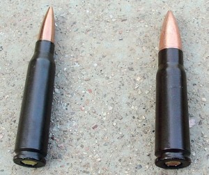
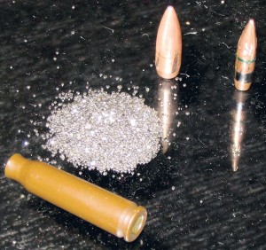
I shot the 5.8mm standard load with the QBZ95 rifle, averaging three-MOA groups at 100 meters. With a shooter more comfortable with the bullpup layout and a proper zero, 2½-MOA or better accuracy should be achievable with the same 5.8mm ammo-and-rifle combination. From my experience in the Marine Corps, the M855/SS109 5.56mm round has an average two-MOA or better accuracy when fired from the M16A2. The newer M16A4 with its heavier and higher-quality barrel is even more accurate.
The AK-74 and 7N6 5.45mm pairing can do 2½ to three MOA up to 300 meters, but the accuracy deteriorates rapidly past 300 meters. The 5.8mm heavy load fired from the QBU88 sniper rifle is claimed to be capable of 1.2-MOA grouping at 100 meters. In actual service, the QBU88’s accuracy is around 1½ to 1.6 MOA with non-match-grade regular 5.8mm heavy-load ammo. In comparison, the USMC’s new M16A4 SAM-R (Squad Advanced Marksman Rifle) can easily achieve sub-MOA accuracy when using the Mk262 5.56mm ammo. As a whole, the 5.8mm’s accuracy is a substantial improvement over the older 7.62x39mm cartridge. Furthermore, it beats out the 1970s-era 5.45mm and approaches the accuracy of the 5.56mm-and-M16A2/A4 combination.
The results of ballistic tests were published in a Chinese-language magazine. The tests demonstrated that the 5.8mm indeed outpenetrates both the 5.56mm and the 5.45mm, as Chinese engineers stated. However, the test was manipulated to make the 5.8mm look good. A long-barrel QBB95 squad automatic rifle was used instead of the QBZ95 assault rifle for the test. The 5.8mm rounds fired from the QBB95 have a 164-fps (50 m/s) advantage over the 5.56mm fired from the Fabrique Nationale FNC assault rifle. Nevertheless, the 5.8mm’s 100 percent penetration rate of the 10mm steel plate at 300 meters is very impressive.
Realistically, the penetration performance difference between the 5.56mm and the 5.8mm is much closer. Contrary to the rigged Chinese ballistic test, unbiased tests done by the USMC and U.S. Army’s Aberdeen Proving Ground show the 5.56mm M855/SS109 fired from the M16A2 rifle with the longer 20-inch (508mm) barrel has no problem penetrating the 3½mm A3 steel test plate at 700 meters. Even so, the 5.8mm is still a better AP round than the 5.56mm due to its APHC (Armor-Piercing Hard Core)-like projectile design that’s more commonly found on dedicated AP ammo. The only known AP performance data of the 5.8 heavy load is that it penetrates 16mm of mild steel at 85 meters and 3.5mm of hardened steel at 1,000 meters. The 5.8 heavy load is said to outpenetrate the old 7.62x54R at any range.
Many official and unofficial Chinese sources frequently mention how important the 5.8mm’s AP performance is. One possible explanation for the Chinese obsession with AP performance is that the 5.8mm’s AP-ammo-like core was specially designed for use against opponents who are wearing heavy body armor—such as U.S. forces.
Like most AP ammo, the test showed the 5.8mm bullet left a rather unimpressive wound cavity in the ballistic soap block. The 5.8’s wound cavity is one-third smaller than that of the 5.56’s and close to one-half smaller than the 5.45’s cavity. The thick steel jacket and the absence of a cannelure on the 5.8 bullet prevent any fragmentation. The more balanced weight distribution of the solid-lead tip with the steel core in the back also prevents the 5.8 bullet from tumbling early and erratically. Nonetheless, Chinese sources claim the 5.8 has a 60 percent increase in lethality over the 7.62x39mm it replaces.
To date, there are some known issues with the 5.8mm ammo, and most of them trace back to the use of low-cost material or poor quality control in the manufacturing process. The propellant load and bullet weight could be inconsistent depending on the production lot. The propellant fouls the gas system and the barrel with corrosive carbon residue. The primer also has a tendency to rust through after it has been in storage for a long period.
There are other special loads developed for the 5.8 caliber. The 5.8 tracer is marked with a blue-violet-color tip. The two different 5.8 training blanks are the star-crimped base blank and a frangible PVC bullet blank that feeds better and doesn’t require the use of a blank firing adapter. The non-lethal 5.8 rubber bullet is loaded with a full-size roundnose black rubber projectile in place of the FMJ.
DBP87-Velocity
A good question is: “How will the 5.8 perform in combat?” According to China’s Xinhua news agency, the 5.8 round scored its first combat kill recently in Haiti during a firefight between Chinese United Nations peace-keepers and the local rebels. The performance of the 5.8 in urban combat operations will likely be a mixed bag. On one hand, its superb penetration will be suitable for punching through tactical obstacles such as brick walls, metal doors, automobile bodies and masonry debris. On the other hand, the 5.8’s unimpressive terminal ballistics may require multiple hits to neutralize an opponent. The 5.8 will fare better in open environments like desert and mountainous terrain with its longer effective range.
The heavy-load version may look good as an extended-range small-caliber rifle round, but as the replacement for the full-caliber, high-power 7.62x54R it is a miserable failure. It is just physically impossible for the SCHV round to produce anything close to the same amount of hitting power and bullet energy as the larger 7.62 caliber. This is probably the main reason why the Chinese military is slow to adapt the 5.8 GPMG. The claim of the 5.8 heavy load outpenetrating the 7.62 is true, but misleading. The higher penetration comes solely from the 5.8mm’s hardened-steel penetrator, which the all-lead-core 7.62 lacks.
Is developing the 5.8x42mm cartridge really worth the effort? Politics and national pride probably had as much to do with its development as the Chinese military. It seems like the Chinese engineers did a decent job in designing the 5.8 cartridge. The problem is that the Chinese military went on the cheap in manufacturing it. We would only see the real potential of the 5.8 if it were to be made with the same material and high manufacturing standard, such as using a brass case, hotter and non-corrosive propellant, tighter tolerances and good quality control, as the American and European NATO rounds. As of now, whatever edge the 5.8 cartridge has over the 5.56 is not enough to make the difference in real combat. The 5.8 may excel in some areas because it has a slightly heavier bullet, a larger cartridge case and more propellant. However, the performance improvements are small; in most cases they are just 5 to 10 percent. In other areas, such as accuracy and lethality, the 5.56 is still a better round by a comfortable margin over the 5.8. Perhaps, during its early development, China’s SCHV ammo should have been built in 6mm class in the first place.

Large Synoptic Survey Telescope (LSST)

$
0
0


Large Synoptic Survey Telescope (LSST) is a next-generation wide-field astronomical survey telescope being built by LSST Corporation (LSSTC) in collaboration with Association of Universities for Research in Astronomy (AURA) and National Science Foundation (NSF).
The telescope will be located on the Cerro Pachón ridge in the Andes Mountains foothills in north-central Chile. The main telescope will be placed on the highest and largest peak, which provides the best view of the sky.
The LSST aims to conduct a ten-year survey of the sky, which will deliver a 200 petabyte set of images and data products.
Estimated to cost $473m, the LSST will see the first light in 2019 and will become fully operational in 2022.

Large Synoptic Survey Telescope project background

The telescope is being developed by LSSTC in partnership with NSF, AURA, the Department of Energy (DOE), and SLAC National Accelerator Laboratory. Founded in 2003, LSSTC is a non-profit partnership between public and private organisations.

The NSF signed an agreement to support the construction of the LSST in August 2014. It is responsible for the construction of the telescope, site facility, data management system, and education and public outreach (EPO) components of the LSST. It will also carry out project management and system engineering.
The casting of dual-surface primary / tertiary mirror of the telescope began in 2008 and its final polish was completed in February 2015.


The on-site construction started with the traditional first stone-laying ceremony held in April 2015.
In January 2015, the LSST project received funding approval from the DOE for the development of the LSST’s 3,200-megapixel digital camera.
The DOE approved the start of construction for the camera in a 2,000ft², two-storey clean room at SLAC in August 2015.

 “Estimated to cost $473m, the LSST will see the first light in 2019 and will become fully operational in 2022.”


Design and features of LSST

The telescope will help astronomers better understand mysterious dark matter and dark energy, hazardous asteroids and remote solar system, transient optical sky, as well as formation and structure of the Milky Way.
The LSST will be an observing facility and will include a telescope, camera, and data management system. It will survey the complete sky in three nights and will collect tens of petabytes of data and images of the sky, which will be used for identifying near-earth asteroids.
The telescope, with a wide field of view, will feature a three-mirror design and its 3.2 giga-pixel camera will have more than three billion pixels of solid-state detectors. It will use software for data management, as it needs to process more than 30 terabytes of data.
The LSST summit facility will be built on the Cerro Pachón ridge, which is 100km by road from the LSST base facility. It will accommodate a telescope pier, a lower enclosure that supports the rotating dome, a 3,000m² service and operations building, and a separate enclosure for the calibration telescope.

The facility will also have an 80t platform lift to carry mirrors and a camera during installation and maintenance. It will also include dedicated maintenance areas, while the on-site service building will house a dedicated cleaning and coating area for mirrors.

LSST optical and mirror design details

The telescope will mainly integrate three aspheric mirrors, including an 8.4m primary mirror (M1), a 3.4m convex secondary mirror (M2), and a 5m tertiary mirror (M3).
The M1 and M3 mirrors were fabricated from a single piece of Ohara E6 low expansion glass, while the M2 is a convex mirror made of 100mm-thick low expansion glass.
To be located after M3, the camera will integrate a focal plane, three silica lenses, and one filter.

Funding for LSST

The Large Synoptic Survey Telescope project is being financed by the NSF, DOE, and private funding raised by LSSTC.
The total funding for the project is capped at $473m, of which $168m will be financed by the DOE to support the fabrication of the LSST camera.
The project also received donations of $20m and $10m from Charles Simonyi and Bill Gates respectively.

LSST data public outreach

An estimated 10% of the full LSST data will be accessible to the public through the LSST EPO online portal.
The portal will feature EPO Skyviewer, which will present the users with a colour image of the night sky observed by the telescope. It will also enable formal educators to access LSST data through Jupyter Notebook.

Top 20 Politicians for Gun Owners 2016

$
0
0
It’s no secret to anyone who is paying attention that gun rights are in the crosshairs of the political debate.
We no longer live in a time where gun control advocates hide their views behind “gun safety” doubletalk, at this point, the lines have become pretty clear. This year saw a Democratic Presidential Primary where the candidates sought to one-up each other on their support for stricter gun control laws and California just passed some of the most anti-gun legislation in our nation’s history.

The President’s latest executive order relating to ITAR permits will likely put hundreds of small time gunsmiths, already a dying breed, out of business permanently. The United States Supreme Court is up for grabs. We live in perilous times.
Under the circumstances, it bears quoting Jed Eckert: “So, who is on our side?” The good news is, many in Congress. Over the past few years, we have witnessed several tragic mass shootings on our nation’s soil, each followed by loud cries to restrict the rights of all Americans.
politicians
In the face of this overwhelming pressure from the media, the public, and gun control advocates who have waited decades to take advantage of such tragedies, many have stood in the gap. Some Republican, some Democrat, some in positions of leadership and some who are rank and file members of Congress, the list of those who have fought to protect gun rights in thankfully long.
As the 2016 General Election approaches, we wanted to highlight some of those who have stood their ground to defend our most fundamental freedoms. There are thousands of elected officials doing great work in state capitols and legislatures across this country, far too many to review.
Congress alone has 535 sitting members, a fair review of which would fill many volumes of this entire magazine. We chose to highlight ten members from each chamber, ten Senators and ten members of the U.S. House of Representatives who have gone above and beyond in protecting firearms rights.
This isn’t a ranking per se, but a list of honorable mentions—each of these members has contributed significantly to the cause of defeating statutory erosions of the Second Amendment.
Gun rights organizations such as the NRA have access to detailed databases of voting records and are far better qualified than we to make truly objective candidate rankings. We have, however, placed an emphasis on members who are seeking reelection in 2016: every member of the House must stand for reelection every two years while only a third of the Senate is currently running.
So here they are, the Best Politicians for Gun Owners for 2016 according to us.
The House of Representatives:
Paul_Ryan--113th_Congress--
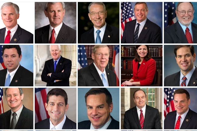
Speaker Paul Ryan (WI)
If you only have one vote in a legislative chamber on your side, you want it to be the presiding officer of that chamber. Speaker Ryan, like Speaker Boehner before him, has held the helm of the House firmly against the rising tide of gun control votes.
Speaker Ryan has been a steadfast supporter of gun rights for his entire political career and is himself both a shooter and a hunter. If your thankful that you haven’t seen federal gun control legislation pass during the Obama Administration, much credit goes to House Republican Leadership including Speaker Ryan.
RRob-Wittmanep. Rob Wittman (VA)
Rep. Wittman was one of the primary sponsors of the Sportsman’s Heritage and Recreational Enhancement (SHARE) Act, which passed the House in early 2016.
The SHARE act will enhance access to public lands for hunting and shooting, protect the right of self-defense, and curtail punitive regulations promoted by environmental extremists.
One of the most important elements of the bill is the Target Practice and Marksmanship Training Support Act, which would allow a greater slice of the federal excise tax on firearms and ammunition to be returned to the states for the use of acquiring land for public target ranges. Rep. Wittman also co-sponsored the Hearing Protection Act, which would remove suppressors from the National Firearms Act.
Bob-LattaRep. Bob Latta (OH)
Rep. Latta Co-Chairs the Congressional Sportsmen’s Foundation and has been a steadfast supporter of the rights of gun owners.
Rep. Latta Co-sponsored versions of the SHARE Act for years, and has helped lead the fight to protect traditional ammunition from regulation by the EPA.

Richard_HudsonRep. Richard Hudson (NC)
Rep. Hudson sponsored legislation in 2015 that would provide for national Right-To-Carry reciprocity which currently has 216 co-sponsors.
Hudson gets A ratings from both NRA and GOA.


Rob-BishopRep. Rob Bishop (UT)
Rep. Bishop has served as the Chairman of the important House Committee on Natural Resources. Last year, Chairman Bishop introduced “Lawful Purpose and Self Defense Act of 2015.”
This key legislation would remove ATF’s authority to interpret the “sporting purposes” clauses in federal law and broaden the category to include self-defense. ATF has used this clause to ban the importation of firearms and ammunition including most 5.45x39mm ammo.
Jason_ChaffetzRep. Jason Chaffetz (UT)
Rep. Chaffetz, who Chairs the House Committee on Oversight and Government Reform, is a strong opponent of gun control laws.
Rep. Chaffetz has helped lead the investigation into “Operation Fast and Furious” and been among the administration’s most vocal critics of its role in that debacle. Chaffetz is also a firm supporter of the rights of suppressor owners.

Cresent-HardyRep. Crescent Hardy (NV)
Though a relatively new member, Rep. Hardy stood fast with his colleagues in voting against the most recent round of gun control efforts.
Rep. Hardy’s support for the rights of law-abiding Nevadans has put him in the crosshair’s of Bloomberg’s Anti-Gun front group “Moms Demand Action.” Hardy’s likely opponent in the general election recently publicly renounced NRA and resigned his membership so, the choice here is pretty clear.
Don-YoungRep. Don Young (AK)
Rep. Young has been fighting for gun rights in Congress since he was first elected in 1973. Don Young is a member of the NRA’s Board of Directors and his list of pro-gun votes in the U.S. House is too extensive to list. Rep.
Young is an avid hunter and shooter and has very much “walked the walk” for decades.

bradley-byrneRep. Bradley Byrne (AL)
Rep. Byrne, who represents Southwest Alabama, has a pro-gun voting record that goes back to his days in the Alabama Senate. Byrne is among the members who can be counted-on to stand firm against whatever gun control proposal comes down the pike.
Among other actions, Byrne co-sponsored a bill to remove common 5.56mm ammunition from the definition of “armor piercing”.

TIM_WALZRep. Tim Walz (MN)
A Democrat, Rep. Walz proves that gun rights are not always partisan issues. Walz Co-sponsored ATF reform legislation back in 2008 and was a lead sponsor in the SHARE Act.
While most congressional Democrats have jumped on the gun control train with both feet, Tim Walz and a few others have stuck to their guns.
U.S. Senate
Marco_Rubio,_,_112th_CongressSen. Marco Rubio (FL)
Even on the national stage as a major presidential candidate, Senator Rubio never wavered from his support for the rights of gun owners. Rubio’s pro-gun record goes back more than a decade during his years as a member of the Florida House. While in the U.S. Senate, Rubio introduced the Firearms Manufacturers and Dealers Protection Act of 2015 to stop the abuses of “Operation Choke Point”, introduced legislation to protect the rights of D.C. gun owners, and supported national Right-To-Carry legislation.
Rubio grew up in a community that saw their rights stripped away by a communist regime and that experience obviously left an indelible mark on his respect for the U.S. Constitution.
Roy_BluntSenator Roy Blunt (MO)
Senator Blunt’s pro-gun voting record is hard to beat and goes back to the 1990s when he was a member of the House. When the media attacked him for being NRA’s top recipient of campaign funds, his campaign’s response didn’t mince words “He is glad to have the support of the overwhelming majority of Missourians who agree with him that our right to keep and bear arms is enshrined in our Constitution and is worth protecting.”
Then Congressman Blunt co-sponsored a national RTC bill and Senator Blunt voted to support the Protection of Lawful Commerce of Arms Act. Blunt voted in opposition to magazine restrictions and against the Toomey-Manchin background check Amendment.
Rob-POrtmanSenator Rob Portman (OH) 
As a Congressman, Senator Portman stood against the onslaught of gun control bills brought by President Clinton and his allies in the 1990s. Portman voted against the Brady Bill as well as the 1994 Semi-Auto Ban, and voted to repeal the ban in 1996.
As a Senator, Portman voted to protect the firearms industry from predatory lawsuits and voted to repeal the D.C. gun ban. In 2013, Portman cast his vote in-opposition to imposing universal background checks.
Johnny_IsaksonSenator Johnny Isakson (GA)
Besides being a leading advocate for the gun rights of veterans, Senator Isakson has a long history of supporting gun owners. He signed the congressional amicus briefs in both the Heller and McDonald gun rights cases, and voted to for the Lawful Commerce of Arms Act which became law in 2005.


Ron_JohnsonSenator Ron Johnson (WI)
Sen. Johnson chairs the Homeland Security and Governmental Affairs Committee where he had been a leading voice for gun owners. Johnson opposed the UN Arms Treaty and voted against a Blumenthal-sponsored amendment that would have banned magazines with capacities exceeding 10 rounds.
Johnson voted against S. 649 in 2013 and the mandatory background check proposal called the Toomey-Manchin Amendment that same year.
Richard-ShelbySenator Richard Shelby (AL) 
Senator Shelby’s political career dates back to the 1970s: he has been elected to the State Senate, the U.S. House, and has served in the U.S. Senate since 1987. Shelby’s voting record includes voting against the 1994 semi-auto ban, voting in favor of protecting gunmakers from frivolous lawsuits, voting for national RTC reciprocity, and voting to end the D.C. gun ban.
As Chairman of the Senate Appropriations Committee, Senator Shelby has been a key ally to gun owners and gun rights advocates.
John_CornynSenator John Cornyn (TX)
Following the Orlando shootings, when an effort was made to ban the sale of firearms to anyone on a secret “Terrorist Watch List”, Senator Cornyn led an effort to pass legislation that would bar real terrorists from legally obtaining guns while protecting the rights of all Americans.
Senator Cornyn filed a national RTC bill in 2015 and when the Obama Administration proposed placing the names of disabled Americans into the NCIS as “prohibited persons”, Cornyn introduced a bill to stop it. Cornyn voted for the Protection of the Lawful Commerce of Arms Act and voted to oppose mandatory background checks in 2013.
Chuck_GrassleySenator Chuck Grassley (IA)
As Chairman of the Judiciary Committee, Sen. Grassley is in a tremendously powerful position when it comes to gun control legislation.
Grassley has fought efforts to disarm veterans, voted against the 1994 semi-auto ban, voted to protect against gun manufacturer lawsuits, and has opposed efforts to implement mandatory background checks including the Toomey-Manchin Amendment.
Mike_CrapoSenator Mike Crapo (ID)
Idaho’s Mike Crapo has led the fight for gun owners’ rights while on federal lands. In 2015, Crapo introduced legislation that would allow for firearms on the 11.7 million acres owned or operated by the U.S. Army Corps of Engineers. Previously, Crapo led the successful effort to allow for carry in national parks and wildlife refuges.
Crapo voted to protect the gun rights of D.C. residents, co-sponsored the bill to end predatory lawsuits against the gun industry, and opposed the Toomey-Manchin Amendment in 2013.
Kelly_AyotteSenator Kelly Ayotte (NH) 
Senator Ayotte is in a tough battle for reelection in a comparably liberal New England state and the media is vehemently attacking her for her pro-gun record. Though Ayotte’s efforts to reach a compromise on the terror watch list issue has angered many gun rights supporters, her actual voting record is solid. Ayotte voted to defeat the universal background check amendment in 2013 and, as the Granite State’s Attorney General, she signed the pro second amendment amicus brief on the Heller case in 2008.
Ayotte’s opponent, current Governor Maggie Hassan, vetoed permitless carry bills two years in a row as well as legislation to protect gun owners’ rights during emergencies. She did, however, sign legislation to allow for suppressor use while hunting. Voters can assume that Hassan, who received a “D” rating from NRA during her last Governor’s race, would not be a better choice when it comes to gun rights issues

ConTech Engineering Conveyor Technology

Warehouse Conveyor

How to Design a Super Simple Sensor System for Industrial Monitoring Applications

$
0
0
This article describes an Ethernet-connected subsystem of a larger modular sensor system designed for industrial or smart home sensing and monitoring. We will discuss a custom sensor subsystem developed for this application.
Creating custom sensor solutions for home or automation typically requires a great deal of customization. A variety of sensors from perhaps several manufacturers are collected on a circuit board, firmware must be engineered, and a user interface or dashboard created. It isn’t overwhelmingly difficult work—but it can be rather tedious and time-consuming. The customization aspect may also make it cost-prohibitive in many use cases.
The idea behind this project was to create a “Super Simple Sensor System” that allows a wide variety of input and output nodes to be linked together with a common protocol with the fewest number of wires possible and low upgrade/replacement cost. This subsystem will hopefully spark creativity in your designs but it is not a market-ready product.
The inspiration came from the wonderfully designed Makeblock Neuron line of children’s educational toys. Multiple sensors and inputs (temperature, humidity, joystick, buttons, etc.) are connected with a variety of outputs and interfaces (LED display, buzzer, etc.) and all of the devices connect via magnetic spring-loaded pogo-pin connectors.

Project overview: Each node connects to its neighboring node with power, ground, and two UART connections. Click to enlarge.

Choosing a Communication Protocol

Each node in my project has an inexpensive microcontroller built in. Sensor or mechanical input data is sent to the microcontroller through the interface appropriate for the sensor (SPI, I2C, CAN, 4-20mA, etc.) and the microcontroller then converts the data to a common interface (UART, USB, etc.) for transmission to neighboring nodes.
In this case, I chose UART as the common bus protocol. Data is read from the neighboring node on the left, data from the current sensor is added to the stream, and then all of the data is passed to the neighboring node on the right.
Each input node adds to the datastream, perhaps with a byte identifying data length, a node identification byte, and the data. Designers who wish to augment the system need only design a single node; this retains modularity of design and allows a catalog of devices to be connected quickly and easily.


Data is continually passed in daisy-chain fashion from one node to the next until it reaches an output node. There the output devices (flashing alarms, LCD displays, buzzers, etc.) read the datastream for information that pertains to them and act accordingly—passing the data along the entire time.
This would work well enough for a three-wire interface (VDD, GND, Data) with one UART bus, but would require that all input nodes be placed before output nodes. By adding a second UART bus, bidirectional information can be passed and nodes can be added in any configuration. Alternatively, the second line might be used for microcontroller software updates, as a heartbeat monitor, or reserved for future use.
You can make life easier by using magnetic pogo-pin connectors in your design.

Image of magnetic pogo pin connectors courtesy of Shenzhen Like Hardware Electronics, Co. LTD.

As indicated above in the block diagram, the Tx/Rx lines (for both UART0 and UART1) extend to opposite sides of the board. This is for several reasons.
First, and perhaps most important, this allows simultaneous programming/debugging and use. The microcontroller programming interface shares pins with UART0 (i.e., the programming signal and the UART signal are both routed to the same physical pin), so testing a receive and transmit sequence, which happens on opposite sides of the board, while connected to the debugger, requires that one of the two data pins from UART1 be on either side of the board.
Second, it allows a single UART bus to be utilized in a three-wire configuration (i.e., power, ground, Tx on one side and power, ground, Rx on the other side).
Lastly, it might simplify the firmware by allowing data to be received and transmitted using the same bus instead of being copied from a receive bus to a separate transmit bus each time it enters a node.

Designing with Industrial Communications in Mind: About the Subsystem

Sensors and displays on a factory floor tend to be ignored over time. Data must be moved from the factory floor to a central location in the building, or perhaps across town to a monitoring location. To satisfy that requirement, I chose to use a wired Ethernet connection. Cat5 and Cat6 wiring, usually already installed at a location, can transmit data over long distances in a LAN, and when connected to WAN, can move data anywhere in the world. The MQTT protocol is designed for M2M (machine-to-machine) communication, and an MQTT broker can easily be established to move the data from interface node to interface node, all the while being secured withTLS1.3.
Once the data reaches its destination in the LAN, or the Internet, a programmer can capture the data to create a graphical user interface, sometimes referred to as a “dashboard,” that managers and controllers can view. Unfortunately, those displays tend to gradually be ignored over time as well. The current trend in automation is to create automated texts, emails, or other alerts that can be sent directly to workers, and then if the worker does not correct the errant situation in a timely fashion, notify the employee’s direct supervisor.
The critical parts of this project require that I have two independent UART buses and one Ethernet interface. For the Ethernet interface, I chose the WizNET W5500. This highly integrated IC implements the TCP/IP stack, the 10/100 Ethernet MAC (media access control), and the PHY (physical layer). I don’t have much experience with the TCP/IP stack, UDP, ARP, ICMP, etc., and this IC allows me to use up to 8 sockets over SPI—a protocol I am familiar with.  
I selected the MSP430FR2633 as the microcontroller. While the MSP430FR2433 would also be able to control the W5500, I knew I would have some unused GPIO pins, and I liked the option of creating a low-costcapacitive-touch control panel in the future. The 2433 does not support capacitive touch, so I opted for the 2633. All other ICs used in the project support the W5500 and the MSP430FR2633.

Power

Each node in the system shares a common 5VDC rail.  The 5V supply is generated by one board that serves as the power source for the entire network, and then each board uses two TLV757P LDOs to regulate the 5V rail to 3.3V for analog circuitry and 3.3V for digital circuitry.  This is a four-layer board, with the top and bottom layers used for signals and layers 2 and 3 for AVDD and GND, respectively.

The schematic diagram of the power section

Routing of the AVDD and DVDD lines provided a challenge on this 4-layer board. AVDD (shown in magenta below) was chosen as the power-plane net because this arrangement seemed to result in easier, cleaner routing. DVDD had to move between layers 1, 2, and 4, which is not ideal. At each transition, multiple vias were used to minimize the impedance.

Shown above is the physical PCB, followed by layers 1-4 of the layout. Layer 2 (AVDD) is shown in magenta, and DVDD is shown in orange.

Ethernet Connectivity

Almost all devices that are hard-wired to the Internet have an 8P8C RJ45 jack. Either built into the jack or very close to the jack there is a pulse transformer. The pulse transformer galvanically isolates the integrated circuit from the cable. The isolation provides protection from DC fault conditions and eliminates problems associated with differences in the ground potentials of the transmitter and receiver. The transformer also functions as a differential receiver that suppresses common-mode noise, such as electromagnetic interference that is generated from high-power equipment and coupled equally into two tightly twisted signal wires.  
The two options for circuit integration are an RJ45 jack with an external pulse transformer, or an RJ45 jack with integrated pulse transformer. The integrated option is often called a “MagJack” and is generally easier to use, but a tad more expensive. You only need to access two of the four pairs of wires for 10/100 communication. The other two pairs are not used at all! When I was selecting parts for this project, this thought didn’t occur to me, and I rejected several proposed MagJacks because they only provided access to two pairs of wires and had six-pin footprints—I needed an 8P8C jack, with two LEDs (each LED has separate anode and cathode pins), so I was searching for twelve-pin footprints or greater. Woops! Only four of the eight conductors are used. The moral of the story is this: If you’re not going to use all eight conductors, don’t pay for magnetics for the other two pairs of wires—the RJ45 jack will be the same size and perhaps a bit cheaper.
As you can see below, R7-R10 are damping resistors. I estimated their values based on other reference designs. They are necessary to prevent overshoot and ringing in the circuit. Testing would have to reveal if the lines are over/under/critically damped and the values adjusted accordingly. The transmit pair are pulled up to DVDD through 49.9Ω resistors, and the center tap is connected to DVDD through a 10Ω resistor and decoupled with a 22nF capacitor to ground. The receive pair passes through the damping resistors where it encounters two capacitors. The pair are tied through two 49.9Ω resistors to a 0.01 µF decoupling capacitor per manufacturer recommendation—they are further pulled up to DVDD through the center tap of the transformer winding.

The MagJack circuit for my WizNet W5500 implementation.

Wiznet W5500

From a hardware perspective, the WizNet W5500 is a pretty straightforward addition to the circuit. An external crystal oscillator must be included and a half-dozen or so analog decoupling capacitors are needed—one for every AVDD pin. Pins 43-45 are used to select the network mode. I included pads for solder bridges should it be necessary to use something other than the default configuration (as it turned out I didn’t need to change the mode).
The crystal oscillator manufacturer recommended the removal of copper from directly underneath the crystal. And I used ground pours to attempt to isolate the crystal’s output from the W5500 SCLK input line, although it was likely not necessary.

WizNet W5500 schematic shown above.

MSP430FR2633

The MSP430FR2633 is the latest microcontroller that I’ve been working with and I’ve used it for a few projects now (including this capacitive touch project). If you have trouble using it, I've found that the Texas Instruments is supportive of engineers in their E2E forums, where application engineers respond to most questions/requests.  
The MCU is programmed with the MSP-FET programmer and debugger through GCC, IAR, or Code Composer Studio. One of the reasons I enjoy working with this MCU is because it has dedicated capacitive touch input pins. This means that buttons/switches/sliders can be added to a control panel for only the cost of the additional PCB, or at no cost if the capacitive-touch elements, the MCU, and the other required components are incorporated into a single PCB. See my other article on the MSP430FR2633 for more details.

The MSP430FR2633 schematic with debounced reset circuit is shown above.

The MCU implementation on a PCB is rather simple—just a few decoupling capacitors and a reset circuit are all that is needed. The debounce circuit on the reset switch follows the datasheet recommendation.

Voltage Level Converters

While not strictly necessary, I added two logic-level converters to the UART datalines that come off of the MSP430. Since the supply voltage coming into the board is 5V, I chose to make the dataline signals 5V, as well. This is a somewhat arbitrary choice and a very good argument could be made for keeping them at 3.3V (which is the supply voltage used by the MCU).

Part Placement

With the exception of the MagJack and power LED, all parts were placed on the top of the board. The MagJack sits away from other components, and the copper underneath the MagJack has been removed from all layers of the board so that the magnetics inside the jack will not influence any other parts of the circuit. Differential pairs are routed outside the footprint of the device in as little distance as possible.
The Wiznet W5500 is located in the center of the board along with all of its support circuitry, and the three unused solder-bridge pads can be seen just above and to the left of the silkscreen table. The MSP430FR2633 is to the right of the WizNet along with header J2—which provides four capacitive touch pins, one DVDD pin, and three GPIO pins. These are for a future user interface panel that holds four capacitive-touch pads and three LEDs. Test pads are provided for every digital signal line with the exception of the differential traces.

Project PCB. Click to enlarge.

See the video below for more information.


This subsystem demonstrates how to potentially integrate a large number of sensors and displays in a factory or home and collect data over long distances using MQTT.
We create projects that hopefully inspire ideas in your designs.  If there is anything you’d like us to consider making, please leave a comment below.

How to Use Scilab to Analyze Frequency-Modulated RF Signals.

$
0
0
Computing a discrete Fourier transform can help you to analyze the ways in which RF modulation affects the spectrum of a carrier signal.


The frequency-domain effects of amplitude modulation are fairly straightforward: the fundamental mathematical operation in an AM system is multiplication, and multiplication causes a spectrum to shift such that it is centered on a new frequency. The mathematical relationship that forms the basis of frequency modulation is more complicated:

xFM(t)=sin(ωCt+txBB(t)dt)

As you can see, a frequency-modulated signal is created by adding the integral of the baseband signal to the argument of the sine function that corresponds to the carrier. In other words, the carrier is sin(ωCt), meaning that it is a sine wave with angular frequency ωC and no phase term, and the FM waveform is the carrier with the addition of a time-varying phase term equal to the integrated baseband signal.
Phase modulation is closely related to frequency modulation:

xPM(t)=sin(ωCt+xBB(t))

Thus, if you want to analyze a phase-modulated signal, almost everything in this article will be applicable. All you have to do is use the baseband signal, instead of the integral of the baseband signal, as the time-varying phase term.

Integrating the Baseband Signal

Let’s start by creating the baseband and carrier arrays. Note that the sampling frequency and the buffer length have increased by a factor of ten compared to what we used in the previous article; I did this because I wanted the higher-frequency portions of the modulated waveform to have more samples per cycle.

BasebandFrequency = 10e3;
CarrierFrequency = 100e3;
SamplingFrequency = 1e7;
BufferLength = 2000;
n = 0:(BufferLength - 1);
BasebandSignal = sin(2*%pi*n / (SamplingFrequency/BasebandFrequency));
CarrierSignal = sin(2*%pi*n / (SamplingFrequency/CarrierFrequency));
plot(n, BasebandSignal)
plot(n, CarrierSignal)


Now we need to integrate the baseband signal. Computing an indefinite integral of a digitized waveform is not particularly straightforward. Scilab does have a command, called integrate(), that can help us with that task, butintegrate() is almost a topic unto itself, and consequently I’m going to use a simpler method in this article and discuss the use of the integrate() command in the next article.
The simpler method that we’ll use for the time being is based on the following observations:
  1. The baseband signal is a uniform, single-frequency sine wave.
  2. The indefinite integral of a sine wave is a negative cosine wave (plus a constant; in our case the constant will be zero).
So all we have to do is change the BasebandSignal = sin(...) command to BasebandSignal_integral = –cos(...):

BasebandSignal_integral = -cos(2*%pi*n / (SamplingFrequency/BasebandFrequency));
plot(n, BasebandSignal)
plot(n, BasebandSignal_integral)

Blue is the sine version, red is the negative cosine version.

Frequency Modulation in the Time Domain

Now we are ready to generate the FM signal. All we have to do is take the command used to create the carrier waveform and add the array BasebandSignal_integral to the argument of the sin() function.

ModulatedSignal_FM = sin((2*%pi*n / (SamplingFrequency/CarrierFrequency)) + BasebandSignal_integral);

Here is the result:

plot(n, ModulatedSignal_FM)


Don’t worry, the frequency modulation is in there somewhere. The problem is, you can’t see it because the frequency variations are too small relative to the carrier frequency. This is where the modulation index comes in. The modulation index, denoted by m, is used to increase (or decrease) the amount of frequency variation caused by a given baseband value:

xFM(t)=sin(ωCt+mtxBB(t)dt)

If we incorporate a modulation index of 4 into the command used to generate the FM data, the effect of the modulation is much more apparent:

ModulatedSignal_FM = sin((2*%pi*n / (SamplingFrequency/CarrierFrequency)) + (4*BasebandSignal_integral));
plot(n, ModulatedSignal_FM)


We can add the baseband and the integrated baseband into the plot, just in case you want to ponder the relationship between these two signals and the FM waveform.

plot(n, BasebandSignal)
plot(n, BasebandSignal_integral)


FM in the Frequency Domain

The following commands will produce a frequency-domain representation of the FM signal.

HalfBufferLength = BufferLength/2;
HorizAxisIncrement = (SamplingFrequency/2)/HalfBufferLength;
DFTHorizAxis = 0:HorizAxisIncrement:((SamplingFrequency/2)-HorizAxisIncrement);
FM_DFT = fft(ModulatedSignal_FM);
FM_DFT_magnitude = abs(FM_DFT);
plot(DFTHorizAxis, FM_DFT_magnitude(1:HalfBufferLength))
xlabel("Frequency (Hz)")


There are two characteristics here that I want to mention: First, the sideband amplitude can be higher than the amplitude of the component at the carrier frequency. Second, the modulated bandwidth (about ±70 kHz relative to the carrier frequency) is much larger than the bandwidth of the baseband signal (i.e., ±10 kHz).
It’s important to understand, however, that the specific features shown above are not present in all cases of frequency modulation. Various factors affect the characteristics of FM spectra; for example, if we lower the modulation index to 2, we get the following:


If we return the modulation index to 4 and then reduce the baseband frequency by a factor of 2, the spectrum changes to this:


Conclusion

I haven’t extensively studied frequency modulation from the perspective of theoretical analysis, but as far as I can tell it is quite difficult to predict the characteristics of an FM spectrum based on mathematical relationships between the baseband and the carrier. This is a great reason to use Scilab (or MATLAB, or Octave) for frequency-domain analysis of FM systems. I hope that this article has provided a good introduction, and we’ll continue the discussion in the next article.

BrainChip to Release Biologically Inspired Neurmorphic System-on-a-Chip for AI Acceleration

$
0
0
BrainChip has announced the Akida Neuromorphic System-on-Chip (NSoC), the first production-volume artificial intelligence accelerator utilizing Spiking Neural Networks (SNN).
BrainChip has announced the Akida Neuromorphic System-on-Chip (NSoC), the first production-volume artificial intelligence accelerator utilizing Spiking Neural Networks (SNNs). 

Image courtesy of BrainChip.

The US-based company, which also has offices in France and Australia, specializes in neuromorphic computing solutions for AI, taking inspiration from how the neuron works and translating that to digital logic. Their recently announced NSoC promises high performance with low power using SNNs that are based on basic logic functions using CMOS gates without requiring the use of power-hungry GPUs. 
The Akida NSoC can interface with a variety of sensors for processing digital, analog, audio, dynamic vision sensor, and pixel-based data. Once received by the NSoC, the data is converted into a spike which is then processed by the chip’s neuron fabric where the SNN model is hosted. The NSoC can also interface with co-processors using PCIe, USB 3.0, UART, CAN, and Ethernet.

Image courtesy of BrainChip.

BrainChip is betting on the expectation that the AI acceleration market will be worth more than $60 billion by 2025, and that AI computing at the edge will be an increasingly sought after application.

What Is a Spiking Neural Network?

The Spiking Neural Network is the backbone technology behind the Akida NSoC. SNNs mimic neuron behavior more closely than more traditionally used Convolutional Neural Networks. 
In the spiking neuron model, a neuron will only fire if a certain potential (or state) is reached within its "membrane"; a threshold must be met before it reacts and propagates information to other neurons. And in turn, those neurons will react and behave according to their own potential thresholds. Time is also taken into consideration by each neuron, with the membrane potential decaying over time.
Using SNNs, the Akida NSoC is supposed to be highly efficient at learning with minimal training data, and able to associate information more similarly to the human brain.
SNNs were described by neural network expert Wolfgang Maas as being the "third generation of neural networks" as far back as 1997. While not exactly a new neural network model, only a handful of attempts have been made to implement it in hardware:
  • The analog computing Neurogrid  by Stanford University in 2009
  • The SpiNNaker network at the University of Manchester using ARM processors and massive parallel computing
  • The 5.4 billion transistor TrueNorth processor by IBM in 2014

Applications Across Domains

Some examples of applications of the Akida NSoC include:

Vision Systems

The Akida NSoC is expected to be particularly adept at object classification, pairing well with pixel-based, LiDAR, or dynamic vision sensors for use in robotic/drone navigation, autonomous driving, or surveillance. 
Using an SNN modeled for object classification, the NSoC is reported to consume less than 1 watt and can classify data from the CIFAR-10 data set at a rate of 1,400 images per second per watt. 

Image courtesy of BrainChip.

Surveillance

The Akida NSoC’s ability to learn with minimal training data also makes it useful for surveillance and law enforcement. The BrainChip Studio software works with the NSoC to process images with resolutions as low as 24x24 pixels for face detection and classification. This is certainly ideal in the field where operators likely do not have access to multiple images of a suspect’s face, or only have low-resolution security footage to work with. 
When the Akida NSoC is paired with the BrainChip accelerator, up to 600 frames can be processed simultaneously over 16 channels using 16 virtual cores, using 15 watts of power.

Samples of the Akida NSoC are expected to be available Q3 of 2019.
Viewing all 1099 articles
Browse latest View live