Quantcast
Channel: LEKULE
Viewing all 1099 articles
Browse latest View live

Integration of Isolation Products to protect from Electrostatic Discharge

$
0
0
In any high voltage and electrical noise system, the electrostatic discharge (ESD) immunity, an important aspect of electromagnetic compatibility (EMC), is a key consideration in choosing a galvanic isolation device.

An ESD can strike across isolated electrical systems. This does not relate to the protection devices on the printed circuit board.

International Safety Standards

The international standard IEC 61000-4-2 specifies system level immunity performance. The strike event sample is charged human discharging through a metallic tool to a system in an application environment of end customer’s typical operation.

The qualification requirement can be as high as 8000 volts contact discharge and failure is soft functional type or the hard physical damage type. This is different from the component level of ESD human body model where event example is charged human discharge through the skin to a component IC in a controlled environment of factory production and assembly. The qualification requirement is lower voltage and failure is hard leakage or physical damage type.

ESD events and its robustness are important of study and system design. In the medical devices, a recent revision in the medical standard IEC 60601-1-2 to the fourth edition requires higher ESD immunity level. The change addresses the trend of more medical devices use outside the hospital and controlled environments where medical devices can face more electromagnetic noise.

ESD Immunity Test Setup 

Across isolated electrical systems, an optocoupler or isolator must be robust against the ESD. The most ideal performance criteria are to allow no performance degradation during and after testing, while the worst performance criteria are the unrecoverable failure or permanent damage to the device.
In the test setup to simulate ESD immunity test, “AA” size batteries provide power supply and floating ground to an oscillator or crystal that generate signal square pulses to the optocoupler or isolator’s input channel. Then, an ESD gun applies a contact discharge of 8000 volts at the trace of the optocoupler’s LED anode or cathode.

At the other side of the device’s insulation barrier, the output channel is monitored with an oscilloscope. The ESD gun discharge return cable connects to the output side’s power supply reference and earth. In this setup, the ESD zaps across the device’s insulation barrier. The output signal and the device’s current supply consumption are observed for any functional performance degradation (see Figure 1).

ESD immunity test across an optocoupler
Figure 1. ESD immunity test across an optocoupler.

Test Results

Using Broadcom’s optocoupler ACNT-H61L, an ESD contact discharge of 8000V across the optocoupler shows normal functional operation during and after the ESD strike. There is no performance degradation (see Figure 2).

Broadcom optocoupler ACNT-H61L DUT
Figure 2. Broadcom optocoupler ACNT-H61L DUT 

On another digital isolator ACML-7410, ESD contact discharge of 8000V across the isolator shows normal functional operation during and after the ESD strike. There is no performance degradation (see Figure 3).

Isolator ACML-7410 DUT
Figure 3. Isolator ACML-7410 DUT

ESD Immunity Test Results

Galvanic isolation products perform differently in the ESD immunity test. Optocoupler and some isolators do not suffer performance degradation and during the test and still able to function normally after the test. Other devices suffer a loss of function or may even damage permanently as the device gets very hot. It is important to choose a robust isolation product during the system design of ESD immunity.

To see these tests in action, check out the video below.


Can the IoT Save the World by 2040? Dr. Jeremy Rifkin Delivers electronica 2018 Keynote

$
0
0
How do industrial revolutions happen? Here's a look at how electronica 2018's keynote speaker says specific technologies shape our destiny—and why we must embrace change before the year 2040.
electronica 2018 kicked off in Munich on Monday with a keynote by economist Dr. Jeremy Rifkin.
Dr. Rifkin, introduced by Dr. Michael Ziesemer, president of ZVEI, is an economist renowned for his insight on the effect of technology on economic development. He is the founder of the US-based Foundation on Economic Trends, advisor to the EU Commission, and has served as a consultant to world leaders like Angela Merkel on economic development through technology and science.

Upon his introduction to the assembly, Dr. Rifkin immediately forewent the podium on the stage in favor of pacing the aisle between attendees. He also banished photographers to the back, all in hopes of creating a more lecture-hall-esque environment.

Image used courtesy of Irina Gillentine

His hour-long presentation was equal parts assessment of current trends and history lesson, covering previous industrial revolutions and the one that he says we are on the cusp of today. 

Identifying Industrial Revolutions

In the simplest terms, Dr. Rifkin believes that we are poised to enter the third industrial revolution of the last 100 years.
There are three elements, he says, that define the previous major industrial revolutions over this timespan, also known as “technologies to change the world”:
  1. Communication technology
  2. New energy sources
  3. Methods of mobility
With this model in mind, he argues that the first industrial revolution of the last century came from the British in the form of:
  1. Steam-powered printing (communication)
  2. Cheap coal (energy)
  3. Stream engines on rail (mobility)
The second revolution came from the USA and included:
  1. The invention of the telephone (communication)
  2. Texas oil (energy)
  3. Henry Ford’s cheap cars (mobility)


The introduction of (relatively) cheap cars was instrumental in what Dr. Rifkin calls the second industrial revolution

It is Dr. Rifkin’s belief that this second revolution carried the world up until 2008 when the oil that kickstarted it peaked.

Key to understanding Dr. Rifkin’s comments is the concept of climate change. On a global level, many European leaders are vocally supportive of initiatives such as reducing carbon emissions and creating more efficient cities. Rifkin believes this necessary before we pass a tipping point where life becomes unsustainable.

To make an eco-friendly industrial revolution, Rifkin says we will need—before 2040—"new economic vision for the world. And it'd better be compelling." The next generation will be pivotal in paying what he terms “the entropy bill” of the last 200 years of growth, i.e., the cost to the climate that came from reliance on fossil fuels.

Rifkin’s concept for this compelling economic vision is, in short, a single platform: the IoT.

"Things" as Distributed Data Centers: The Lateral Network Effect

The IoT as a platform for industrial revolution, Rifkin says, looks like a nodal system that spans across the world and functions like a brain. He calls this the “lateral network effect” where, like many IoT systems, processing is accomplished laterally across multiple nodes.

One important point Rifkin makes here is that he’s talking about the IoT as in the Internet of Things—not the cloud but actual, physical things.

Buildings, in particular (which he cited as the number one contributor to climate change), are key to this concept. Buildings may be retrofitted with IoT capabilities, turning them into nodes in a larger network of distributed data centers.

Using these nodes in “systems on systems” could help aggregate better efficiency through data. This move towards lateral networks necessitates transparent data processing and use, effectively sharing data and processing across nodes.

Access Over Ownership: The Sharing Economy

The sharing economy, according to Rifkin, came as something of a surprise to economists. Based on previous economic models and attitudes, it was not immediately intuitive that modern people would prefer access over ownership.

Stated simply, a sharing economy is one built on the idea that an individual could prefer steady access to a resource rather than owning it outright.

We’ve seen the effects of interconnectivity on newspapers, music, books, etc., that have needed to adapt, often to a subscription model. Now, says Rifkin, this mentality is moving to the IoT, from the world of the digital to the world of stuff.

The best demonstration of this is Uber, where a new generation would prefer to share a car as a resource than own one themselves. For each car that is shared, Rifkin says, 15 are removed from the road, creating a massive impact on the industry.

One of the most important places that this sharing economy will take effect is in the energy portion of this third industrial revolution. Wind and solar energy sources are seeing the “lateral network effect” occur as small electricity cooperatives spring up across Europe.

wind turbines and solar panels
Rifkin states that renewable energy provided by wind turbines and solar panels are an important aspect of the third industrial revolution.

Rifkin says the growth of wind and solar energy is on an exponential curve. This is especially relevant to a sharing economy because, as Rifkin puts it, “The sun has not sent you a bill. The wind does not invoice you."

The lateral network future, Rifkin suggests, does not include deriving profits by introducing energy into the grid but rather through managing energy throughout a supply chain. For examples of what this might look like, he suggests, “Watch Europe. Watch China.”

The Role of the Electronics Industry

But if we’ve already designed the technologies that comprise the ingredients Rifkin believes will spark our next revolution (e.g., smartphones, solar and wind energy, EVs, the IoT, data aggregation, etc.) why isn’t this revolution already upon us?

"The problem is that we're not scaling,” says Rifkin. “We're doing pilot programs."
While the technologies are being developed, they’re often only demonstrated in one-off smart buildings or other small, exploratory programs. If the revolution is to occur, says Rifkin, these efforts need to scale.

It is here, he says, that the electronics industry will be important: scaling the revolution through the IoT.

At the end of his presentation, Rifkin stated that the “mission of electronics in Europe” should be to “create unity in industry.” He suggests doing this with empathy, the characteristic he considers our strongest suit as a species.
“If we do,” he says, “we have a chance.”
 

The Third Industrial Revolution

This is merely a glance at the complexity of Dr. Rifkin’s presentation, which involved explanations of the theory of thermodynamics, economic concepts such as zero marginal costs, and an assessment of the shift in temperament between generations.

If you’d like to learn more about Dr. Rifkin’s stances on these matters, he’s released a book titled The Third Industrial Revolution. He also worked with VICE Media on a documentary that’s currently free to watch on YouTube, which you can check out below:


electronica 2018 is off to an ambitious start, setting the tone with a thought-provoking keynote speaker who painted a vivid vision of the future of technology.

Rifkin’s presentation drove home electronica 2018's motto "Connecting everything. Smart, safe, and secure" with his points regarding connectivity, investment in the next generation, and a strong sense of optimism that Europe—and Germany in particular—will be the leader in these next steps of technological advancement.


Do you think the IoT will be the key to the next industrial revolution? Let us know your thoughts in the comments below.

ams Introduces Image Sensor for High-Throughput Manufacturing and Optical Sensing Applications

$
0
0
ams has announced its new CSG14K image sensor for Automated Optical Inspection (AOI) that supports the 1” optical format.

The CSG14K image sensor is built around a 3840- by 3584-pixel array, for a 14-megapixel resolution. The 12-bit output will afford the large dynamic range needed to handle the large variations of light intensity that is often encountered in modern manufacturing and inspection environments.


The CV50000, a member of the ams family that preceded the CSG14K.

The CSG14K is a CMOS image sensor that utilizes global shuttering as opposed to global shuttering.

What Is Global Shuttering?

Global shuttering is a method of using an image sensor's shutter that allows clear capturing of even high-speed subjects. As explained by ams, “All pixels are sampled at the same moment in time, producing an image free of distortion." According to ams, they chose global shuttering over rolling shuttering because the latter produces artifacts "caused by the difference in the time of sampling for pixels at different locations in the sensor.”


Rolling shutter vs. global shutter. Image from Oxford Instruments

A camera based on the old rolling shutter mechanism could easily lead to wrong conclusions and unsatisfactory results in an Automated Optical Inspection (AOI) environment.

CSG14K Highlights

Correlated Double Sampling

The CSG14k also utilizes Correlated Double Sampling (CDS), which mandates that a sensor makes not one, but two measurements. The pixel’s output after reset is subtracted from the output measured when actually viewing the sample. This removes visual “noise” and renders a truer representation of the object under inspection.

Smaller Pixels

The sensor’s high resolution is made possible in part by its exceptionally small 3.2µm x 3.2µm pixel size. These are 66% smaller than ams’s previous 10-bit devices.

Versatility

The CSG14k allows designers to program its functionality to operate optimally in a wide range of application environments. A low-power mode is available for situations involving slower frame rates and fewer measurements.

Housing

The CSG14k is housed in a 218-pin, 22mm x 20mm x 3mm LGA package which is compatible with the 1” lenses widely used in small form factor camera designs.

ams’s CMV Family of Image Sensors

The CSG14k is preceded by ams’s CMV family of image sensors.
CMV8000 is an 8-megapixel global shutter image sensor that can run at 103 frame rate (fps) with 10-bit output, or at a lower fps with 12-bit output that supports a superior image quality. Its pixel size is 5.5 µm, and its resolution is 8.4 megapixels


CMV8000 evaluation kit. Image from ams

CMV20000 is a 19.7-megapixel global shutter. Resolution is 5120x3840 (19.7 megapixels) at 30 fps, and pixel size is 6.4 µm.

CMV50000. Unlike other members of the CMV family, this 48 megapixel CMOS image sensor for machine vision applications employs global shuttering and correlated double sampling. Resolution is 7920x6004 (47.6 megapixels) at 30 frames per second.


The CSV50000. Image from ams

Members of the CMV family of image sensors employ sub-LVDS output interface. To ensure compatibility, and perhaps to encourage updates, the CSG14k maintains compatibility with this.

Higher Speed Machine Vision

Machine vision is a wide-open field with many variations of need. Where ams has focused on high resolution, the Phantom S200 and S210 from Vision Research can operate at a far higher frame rate, though with correspondingly lower resolution

Phantom S200 and S210 from Vision Research. Image from Phantom High Speed

For comparison, here are their major relevant specs:

S200

  • Resolution of 640 x 480 pixels
  • Maximum speed at full resolution is 7,000 fps
  • Pixel size 11 µm

S210

  • Resolution of 1280 x 480 pixels
  • Maximum speed at full resolution is 1,730 fps
  • Pixel size 5.6 µm
Another AOI-oriented image sensor just released is the KAI-50140 from ON Semiconductor. Our recent article on that sensor discusses the difference between CCD and CMOS sensors rather than the differences between global and rolling shuttering.


How often do you work with image sensors in your job? What specifications are the most important for your applications? Let us know in the comments below

When An Israeli Air Force F-15 Landed Safely With Only One Wing (Great Footage)

$
0
0


It’s hard to imagine that a pilot could remain unaware of his plane colliding with another aircraft, but that’s precisely what happened one warm, spring day in the Israeli skies in 1983.

In May 1983, an A-4 Skyhawk and an F-15D Eagle were participating in a training exercise over the Negev region when they collided.

The pilot of the A-4 Skyhawk was able to escape his plane before it exploded. But the other plane, an F-15D Eagle, continued on its journey, and the pilot had no idea what had just happened.
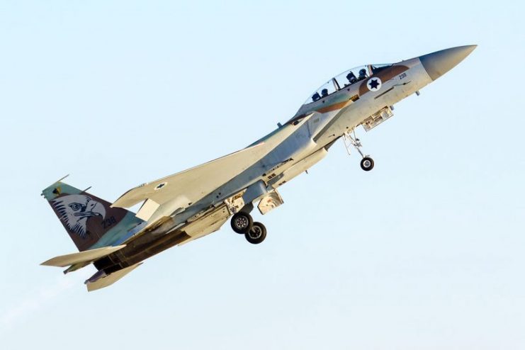
Israeli F-15D Baz ‘957’ (named ‘Markia Schakim’, ‘Sky Blazer’ in Hebrew). Photo: KGyST / CC-BY-SA 3.0
It wasn’t until the plane went into a spin that Ziv Nedivi realized that something was wrong. However, little did he know the true gravity of his situation. Even his navigator, Yehoar Gal, didn’t have a clear picture of what had occurred.

Although one wing was almost completely destroyed, neither man could see this clearly because a haze of vapors had settled over the area where the right wing had been just moments before.
In a statement after the incident, Nedivi said, “At some point, I collided with one of the Skyhawks… at first, I didn’t even realize it. I felt a big strike, and I thought we passed through the jet stream of one of the other aircraft. Before I could react, I saw the big fireball created by the explosion of the Skyhawk.”
A storage site for Israeli Air Force McDonnell Douglas A-4N Skyhawk aircraft, awaiting dismantling.
Once Nedivi understood the situation better (although still not completely), his training and knowledge kicked in. He looked at the navigational computer and saw no indication that anything was amiss.

But others on the ground knew the plane was in trouble, even if Nedivi didn’t. He heard over the radio that the Skyhawk had indeed exploded. He was told by an operator to eject, but once the aircraft was under control again, he didn’t want to abandon it.

“When I got control (again),” he said, “I thought, ‘wait! Don’t eject yet’!” But Nedivi was a student, participating in a combat training class, and by choosing to ignore the radio operator’s instructions, he was flouting his superior’s instructions.
F-15D Eagle (Baz), Israel
Later, Nedivi said, “All I knew was, as long as this sucker flies, I’m going to stay inside. I started to decrease the airspeed, but at that point, one wing was not enough… a second before I decided to eject, I pushed the throttle and lit the afterburner. I gained speed, and thus got control of the aircraft again.”

As he lowered the plane toward the runway, Nedivi released the tail hook, but the speed at which was the plane was traveling completely destroyed it. When he first touched the ground, he was going about 260 knots – twice the speed he should have been at that stage in landing. He came to a final stop mere feet from the end of the runway.

Even then, he still had no idea of the extent of the damage. Nedivi got out and turned to speak to his flying instructor — only then did he realize he’d been flying with, essentially, one wing.
Israeli Air Force 69 Squadron F-15I Raam taking off into the sunset
The F-16 was a valuable asset to the Israeli Air Force, so Nedivi had been directed to land it at Ramon’s Air Base where it was promptly taken for repairs.
This aircraft had, by the time of Nedivi’s “close encounter” in 1983, already taken out four enemy planes during the Lebanon War. After being fixed, it went on to participate in a “shared kill” of a Mi-23 plane in November 1985.

Nedivi was applauded for thinking fast and saving himself and the plane, an important piece of air force equipment. But he admitted that the entire episode came as a shock: “I turned back to shake the hand of my instructor,” he explained after landing, “and then I saw it for the first time – no wing!”
If he had looked around while still in the air and seen nothing but blue sky where a wing should have been, who knows how Nedivi would have reacted? It’s no doubt best for him, and the Israeli Air Force, that he stayed so focused on his mission that day.
 

A Prolific Destroyer of Nazis: Paddy Mayne – Founding Member of the SAS & a Total Hardcore Wild Warrior

$
0
0
 
“Wild maybe, but he was definitely someone you would want on your side.” Colonel Robert Blair Mayne also known as ‘Paddy’ and as a prolific destroyer of Nazis troops and machinery
Robert Blair Mayne, known by the nickname “Paddy,” was one of the most effective Allied soldiers during World War II. In addition to many awards, he was distinguished by phenomenal physical power, mastery of the knife, his exceptional skills as a shooter, and his ability to move silently.
Robert Blair “Paddy” Mayne
Mayne was merciless to his opponents, using any means he could to emerge victorious from the most difficult situations.
In addition, Mayne had the unique ability to assess the situation on the battlefield instantly and assess his own capabilities so as not to put his soldiers at risk. Getting into critical and often hopeless situations, Mayne performed unimaginable and courageous actions that influenced the outcome of battles.

He was also one of the founders of the Special Air Service (SAS).
In order to understand how Paddy Mayne managed to achieve such results, it is necessary to pay attention to his origins and the circumstances by which his character was formed.
He was born on January 11, 1915, in the city of Newtownards, Northern Ireland to a Protestant family who owned several retail businesses in the city.
Lt Col Robert Blair ‘Paddy’ Mayne, SAS, in the desert near Kabrit, 1942.
Paddy was named in honor of his mother’s cousin, Captain Robert Mayne, an officer in the British army who died in battle during the First World War.

While attending elementary school, Mayne became interested in playing rugby and played for the school’s 1st XV and the local Ards RFC team. In addition, he played golf and cricket as well as showing some skill as a shooter at a local club.

After graduation, Mayne decided to become a lawyer and studied law at Queen’s University Belfast. In August 1936, he became a heavyweight-boxing champion among the Irish universities.
Mayne was also the second-line striker of the Ireland rugby team. As part of his team, he won six games, and in 1938, he joined the British Lions during their tour of South Africa.

However, his legal and sports careers were soon prematurely interrupted by the approaching war.
On the playing field, Mayne was a goal-oriented player. Tough sports and the ability to compete with outstanding athletes had given him confidence, endurance, and perseverance. He had the ability to work in a team but also displayed leadership skills.

All these qualities were indispensable and came in useful to Paddy while serving in the SAS.
A heavily armed patrol of ‘L’ Detachment SAS in their Jeeps, just back from a three-month patrol. The crews of the jeeps are all wearing ‘Arab-style’ headdress, copied from the Long Range Desert Group.
Before the beginning of the Second World War, Mayne had joined the Supplementary Reserve in Newtownards. He moved through several regiments and after the evacuation of Dunkirk, Mayne volunteered for the newly formed No. 11 (Scottish) Commando.

In June 1941, acting as a junior lieutenant with No. 11 Commando, Mayne took part in a Syria–Lebanon Campaign.

He was involved with an operation on the Litani River in Lebanon against the French troops of Vichy. Mayne played a distinct role in the raid. For this, his name was mentioned in dispatches and his friend, Lt. Eoin McGonigal, recommended him to Captain David Stirling.

From November 1941 to the end of 1942, Mayne took part in many night raids in the deserts of Libya and Egypt as part of the SAS. There is a claim that he was a pioneer in the use of military jeeps for night raids and single-handedly managed to destroy up to 100 enemy aircraft.

During Mayne’s first successful raid at Wadi Tamet on December 14, 1941, he was awarded the Distinguished Service Order (DSO) and on February 24, 1942, was mentioned in dispatches.
On the night of July 26, 1942, Mayne took part in one of the most successful SAS raids in the desert along with Captain Stirling. Eighteen armed jeeps raided the Airfield of Sidi Haneish. Managing to avoid detection, they destroyed up to 40 German aircraft. They managed to escape, losing two men and three jeeps.

The success of this operation saved the SAS from the dissolution that the regular army had planned.
Mayne developed a bit of a reputation for drinking. Alcohol released all his ferocity and recklessness. He was known to repeatedly start fights and once trashed a dining room.

When Stirling was captured in January 1943, the 1st SAS regiment was reorganized into two separate parts: the Special Boat Section and the Special Raiding Squadron (SRS).

Mayne became commander of the Special Raiding Squadron and led a unit in Italy and Sicily until the end of 1943. On July 10, 1943, in Sicily, he performed two successful operations: the first to seize batteries during which he killed 200-300 Italians and the second to secure the town of Augusta. For this, Mayne was awarded a bar to his DSO.

In January 1944, he was promoted to lieutenant colonel and was appointed commander of the re-formed 1st SAS regiment. Mayne led the SAS during the war campaigns in Belgium, Germany, Norway, the Netherlands, and France. In operations, he often attracted resistance fighters including French Maquis.

For his leadership, heroism, and close cooperation with the French Resistance, Mayne was honored to receive a second bar for his DSO. The post-war French government awarded him the Croix de Guerre and the Legion d’honneur.

Mayne received a citation for the Victoria Cross but was turned down. The question of why this happened not only arose in the minds of his contemporaries at the time, but was also raised in the British Parliament in January 2006. In spite of a public campaign to reopen the case, the British government refused to award him the Victoria Cross retroactively.

Paddy Mayne was a man who would refuse to obey the orders of his superiors and who violated many articles of the military charter.

However, during the war, he used his best qualities of perseverance and effectiveness to defend the interests of his country and the SAS.

Crazy: General Westmoreland initiated plan to use nukes in Vietnam

$
0
0
 
Just a few days ago, the New York Times ran an extraordinary article about the Vietnam War.
In it were facts that have only recently come to light and illustrate exactly how frustrated the American military and political leadership were with the war and each other.

This news was that General William Westmoreland, overall American military commander in Vietnam from 1968-1972, activated a plan to move and potentially use nuclear weapons against the North Vietnamese.
Recently declassified documents show that Westmoreland was increasingly nervous about the outcome of the siege of Khe Sanh, one of the biggest and longest battles of America’s involvement in Vietnam.

In the end the engagement, which lasted from January to June 1968, proved indecisive. The Vietnamese communists failed to dislodge the Americans from their strategic base, and US forces withdrew from the area voluntarily after the siege had been lifted.
National Security Advisor Walt W. Rostow showing President Lyndon B. Johnson a model of the Khe Sanh area, 15 February 1968
In many ways, Khe Sanh was the Vietnam War in a nutshell: the US inflicted dire losses on the North Vietnamese and their Viet Cong allies, and the Vietnamese were able to engage the Americans in a long prolonged conflict with no clear ending.

Sanh, especially its conclusion, sapped already poor American support for the war at home, and crushed American morale in the field.
An Army 175-mm M107 at Camp Carroll provides fire support for ground forces.
At the time Westmoreland began to act on his ideas, however, the siege was still going on, and not going well for the United States.

People all over the world were comparing Khe Sanh to the French defeat in North Vietnam at Dien Bien Phu in 1954, which essentially put an end to French rule in Southeast Asia.
A burning fuel dump after a mortar attack at Khe Sanh
Khe Sanh began nine days before the North Vietnamese/Viet Cong Tet Offensive, which signaled to many in the West that the Vietnamese War was lost, despite victory on the field. As the siege at Khe Sanh went on, that feeling only grew.
Marine Corps sniper team searches for targets in the Khe Sanh Valley
Westmoreland and the Johnson Administration were worried that a clear North Vietnamese victory at Khe Sanh would put yet another nail in the coffin of American involvement in Southeast Asia, and would cause even greater protest against the war in the United States.

To that end, Westmoreland put in place a contingency plan – one that Johnson did not know about.
3/4 Marines memorial service at Khe Sanh Combat Base
Named “Operation Fracture Jaw,” the plan called for the movement of nuclear weapons from American bases in the Pacific and the United States to Vietnam in case of defeat at Khe Sanh.
On February 10, 1968, Westmoreland communicated with Admiral Sharp, Commander in Chief, Pacific and told him that “Oplan Fracture Jaw has been approved by me.”
Fracture Jaw operation
Westmoreland also communicated with other generals, such as General Earle Wheeler, the Chairman of the Joint Chiefs of Staff, and they discussed implementing “Fracture Jaw” as soon as possible, if circumstances warranted.
Combat on Hill 875, the most intense of the battles around Dak To.
As often happens in Washington, there was a leak, and the National Security adviser to President Johnson found out about the “Fracture Jaw” discussions. Of course, he notified Lyndon Johnson right away.
Note from white house Fracture Jaw
Johnson had grown exceedingly suspicious of the military as the Vietnam War went on, and with good reasons. Among them were the constant promises of victory, followed by requests for billions of more dollars to win the war.

When Johnson found out about “Fracture Jaw” he was furious, and immediately issued an order to Westmoreland that left no room for misunderstanding.
General Westmoreland with Lyndon B. Johnson in the White House, November 1967.
“Discontinue all planning for Fracture Jaw”, read the first point of Johnson’s cable to the general. The other three points stressed the importance of secrecy regarding this incident and all planning of this type:

“Debrief all personnel with access to this planning project that there can be no disclosure of the content of the plan or knowledge that such planning was either underway or suspended” and “Security of this action and prior activity must be air tight [sic].”
Discontinue Fracture Jaw
That was the last anyone heard of “Fracture Jaw” until these documents were recently declassified.
Press conference outside the White House in April 1968.Secretary of State Dean Rusk, General William Westmoreland, President Lyndon B. Johnson, others in background.
Before the Cold War ended, many Americans wondered why the Soviet Union and China prepared for an American first nuclear strike. They told themselves, “We’re not the aggressive ones.

If anyone starts a nuclear war, it will be the Communists.” Unfortunately, both sides had reasons to be suspicious of each other, and looking at the situation solely from the Soviets’ perspective, history would seem to bear out their idea that the Americans might strike first with nuclear weapons.
The United States is the only nation to ever use nuclear weapons in war. The Hiroshima and Nagasaki bombs put an end to World War II.

The point here is not whether the US was justified in their use or not, but that America had–and used–nukes first.
Westmoreland in Vietnam.
After three years and thousands of deaths in Korea, incoming US President Dwight D. Eisenhower used the veiled threat of American nuclear attack to bring the Communists to the negotiating table.
In 1962, John Kennedy went on television to let the American public, and incidentally the Soviets, know that any strike coming from Cuba against the United States would be considered an attack by the USSR on the USA.

We learned much later that the Cubans, much to the Soviets’ chagrin, were prepared to take over Soviet tactical nuclear weapons in Cuba to repel an American invasion.

October 23, 1962: President Kennedy signs Proclamation 3504, authorizing the naval quarantine of Cuba.

In 1981, President-elect Ronald Reagan let it be known by back-channels that he would consider using nuclear weapons to end the Iran Hostage Crisis. On the day Reagan took office, the hostages were released.

The release of the “Fracture Jaw” information has already been blared in headlines in the Russia Times this week, as the new “Cold War” continues.

Myths of WW2: Isn’t The Reality Harsh Enough?

$
0
0
 
Colorized by Jecinci
World War II has been captured on film by Hollywood, written about in both fictional and factual books, and caught in newsreel footage at the time.

Nevertheless, half-baked stories and flat-out lies about it to persist to this day. It’s hard to say why, but perhaps when tales have a glimmer of truth in their origins, it’s just too tempting for some people to avoid inflating them.

For example, some people still think that France essentially rolled out the red carpet for Hitler instead of fighting German occupation tooth and nail. Even more ludicrous, some believe that Hitler danced a little jig when he heard this news. However, the truth is: no they didn’t, and he definitely did not.
France put up quite a struggle, but it was still reeling from World War I, which goes some way to explaining why it took Germany only six weeks to secure its surrender.

As for Hitler dancing at the news, he was indeed shocked that it took relatively little time to take the country over, and was caught on film stepping back when he heard the news. But dancing? No. It would be insulting to French people everywhere to repeat these two stories as fact.
Chief of collaborationist French State Marshal Pétain shaking hands with German Nazi leader Hitler at Montoire on October 24, 1940.Photo: Bundesarchiv, Bild 183-H25217 / CC-BY-SA 3.0
The evacuation of Dunkirk and the circumstances leading up to this event have been repeatedly recreated on film. Remarkably, some people still credit Hitler with ordering his men to take a breather, letting them rest in a kind of salute to Britain and Churchill.

It’s true that German troops were resting and regrouping during the evacuation, but this was at the instruction of an anonymous German general, not because Hitler was showing respect to the English soldiers.

The fact that the Germans didn’t fight the British more arduously during the evacuation is more due to a happy accident of timing.
Troops evacuated from Dunkirk on a destroyer about to berth at Dover, 31 May 1940
Two myths about Hitler himself also persist — one personal, one professional. Concerning the latter, some say that Hitler won the Nazi leadership by just one vote, but in fact, he won by a landslide. The personal myth is that he had one testicle.

This story began to circulate at the end of the war after the Soviets performed the autopsy on Hitler’s body following his suicide.

For years, many insisted it was true, including a medic who treated Hitler in World War I. But there is no conclusive, documented evidence to support this notion.
Hitler, at the window of the Reich Chancellery, receives an ovation on the evening of his inauguration as chancellor, 30 January 1933.Photo: Bundesarchiv, Bild 146-1972-026-11 / Sennecke, Robert / CC-BY-SA 3.0
Some myths about the war sprang from good intentions, like the one in which British planes destroy a German aerodrome. It arose from a book, Berlin Diary, written by war correspondent, William Shirer.
His entry in 1940 claims he heard of British bombers doing this, but the question it begs is: why? Different versions of the story surfaced, such as German planes attacking British airstrips, but again: why? No source for these stories has ever come forward to confirm the account in Shirer’s book.
Shirer in Compiegne, France, reporting on the signing of the armistice. 
Germany was not the only country around which false narratives arose after the war. Japan had its share as well.

Critics of the U.S. atomic strikes against Nagasaki and Hiroshima claim that there was no need for this drastic step because Japan was ready to surrender. On the contrary, there is documented evidence that demonstrates the country’s intention to combat any invasion on its soil.
Atomic bomb mushroom clouds over Hiroshima (left) and Nagasaki.1945
Furthermore, evidence also suggests that it was planning an invasion of the U.S. Japan fervently believed the U.S. could not survive another attack like Pearl Harbour so, before the bombs fell, it was actively planning another attack.

But once the two cities were virtually demolished, Japan signed surrender papers on August 15, 1945.
Representatives of the Empire of Japan stand aboard USS Missouri prior to signing of the Instrument of Surrender.
Another fallacy that swirls around Japan is that one of its wartime leaders in the Philippines, General Tomoyuki Yamashita, found and hid millions in gold and other treasures.

No corroborating evidence was ever offered for this theory, and the general certainly wasn’t talking during his trial for war crimes in 1945. But at least one person bought this tale: the late president of the Philippines, Ferdinand Marcos. He invested time and resources pursuing this myth, all to no avail.
Yamashita (second from right) at his trial in Manila, November 1945
In Germany, the fiercest – and most feared – of Hitler’s troops was the SS. Led by Heinrich Himmler, its mandate was to help create a “master race” made up of Aryans: men of pure, German blood.
At first, Himmler stuck to his principle of recruiting only white men with the correct racial profile. But by 1944, many of these so-called “racially pure” men had died in battle, and Himmler needed more men. By the war’s end, the group had members who were Spanish, French, and even had Russian-German ancestry.
Himmler, Ernst Kaltenbrunner, and other SS officials visiting Mauthausen concentration camp in 1941.Photo: Bundesarchiv, Bild 183-45534-0005 / CC-BY-SA 3.0
Russia is the center of a different sad tale: that bone fields that existed near Volgograd, then Stalingrad. Many men died on the Eastern Front, with some estimates running into the millions. But an Austrian journalist’s claim in the 1980s that they were all put in a mass grave there was a pure exaggeration.

Another story about Russia includes its scientists and biologists, who were purportedly trying to create a “master race” of their own to combat the Aryans.

These creatures were able to conquer all their fear, go without sleep, and serve as slaves to their Soviet masters. No doubt the Russians did bizarre medical experiments just like their German counterparts, but no race of “super slaves” ever emerged.
Ilya Ivanovich Ivanov – a Russian and Soviet biologist.He may have been involved in controversial attempts to create a human-ape hybrid.
Other myths are innocuous, and even a little humorous. A “graveyard of cars” in Belgium was not created by U.S. soldiers stealing German vehicles.

The truth is blander: people abandoned cars, built in the 1960s and 1970s, at a specific locale, which was finally cleaned up in 2010.
A “graveyard of cars” in Châtillon, Belgium.Photo: Tim De Waele.be CC BY-NC 2.0
Some people claim that the expression “the whole nine yards” arose from the measure of a machine gun’s ammunition belt. However, the term comes from American baseball, a reference to the nine innings in a regulation game.
An armorer of the 15th U.S. Air Force checks ammunition belts of the .50 caliber machine guns in the wings of a P-51
The tale of a German submarine being forced to surrender because of a malfunctioning toilet was based on truth but exaggerated.

The toilet was not overflowing, as legend has it. The technology was new at the time, and the sub’s captain misused it with the result that he had to surface to avoid the leaking gas poisoning his crew. The British Navy spotted the sub, just off the Scottish coast.
A model of German Submarine U-47 viewed from the side.Photo: Rama CC BY-SA 2.0
Another false story is that Lee Marvin and Bob Keeshan, also known as Captain Kangaroo, served together at Iwo Jima. Both did indeed serve in the U.S. Army, but at different times and in different locales.

This particular tale sounds like something manufactured by a Hollywood studio’s P.R. department to boost morale. Why no one checked it before it stuck is a mystery.
Bob Keeshan and comedian Nipsey Russell in the Treasure House on the television program Captain Kangaroo.1976
As odd as it sounds, a few Korean men did serve on the German side during the war and were captured by U.S. troops at Omaha Beach in 1944. These men had previously been captured by the Germans and forced into service by them.
An unidentified man in Wehrmacht attire (left) following capture by American paratroopers in June 1944 after D-Day.

These and other stories about the war continue to circulate because society is fascinated by World War II. Despite the many true tales of heroics and tragedy that actually occurred, we are still enthralled by what we don’t understand.

Why learn about the horrors of lab experiments conducted by Russian biologists when we can imagine a fictional story of a Soviet super slave? Perhaps our willingness to buy into false narratives says more about us as an audience than it does about the absurd stories themselves.

Battle of Iwo Jima with Amazing Video and Combat Photos

$
0
0
 
Although a rather small region, Iwo Jima distinguishes itself in the history of warfare as one of the most heavily fortified regions ever known. It was targeted by the Americans due to its strategic location near the Japanese mainland.

On one side was the United States Marine Corps, determined to serve their country by taking over the island, and on the other side of the battle was the Imperial Japanese Army (IJA), determined to fight until the last man, to stop the American invasion and protect their homeland. What ensued on the 19th February 1945, running for over five weeks, would be arguably the bloodiest battle of the Pacific Campaign.

The island had three airfields and would be a staging area for the projected invasion of the Japanese home islands code-named: Operation Downfall.
LVTs approach Iwo Jima.
The Japanese were in poor defensive shape after having suffered severe losses against Allied forces in prior battles of the Pacific. Thus, the success of the invasion was already certain. However, knowing that victory was a luxury they couldn’t afford, the Japanese forces in Iwo Jima, led by Lt. Gen. Tadamichi Kuribayashi were tasked with inflicting heavy casualties on the Americans in the hopes of making the Allies begin to doubt an invasion on Japan itself.

Instead of the traditional Japanese system of direct engagement along the beach, Kuribayashi pulled his forces deeper into the Island. He employed a dense network of bunkers and pillboxes, hiding hundreds of landmines, mortars, and artillery all over the island. Every high and low place of Iwo Jima was surveyed to be completely submerged in Japanese defensive fire. Furthermore, a handful of Kamikaze pilots were kept on standby. Iwo Jima would become distinguished an incredibly tough nut to crack for the Allied forces.
A U.S. Marine firing his Browning M1917 machine gun at the Japanese.
Naval bombardments and air raids against Iwo Jima commenced on the 15th of June, 1944 ahead of the D-Day which was the 19th of June. Just two days into the constant bombardment, America’s USS Blessman ship lost about 41 personnel including 16 members of her Underwater Demolition Team (UDT) due to shelling from the Japanese.

Also during the pre-landing bombardments, the USS Pensacola was hit by a Japanese battery causing 17 deaths. The USS Leutze was also hit and suffered 7 deaths while aiding 12 vessels in a failed attempt to go ashore.
A flamethrower operator of E Company, 2nd Battalion 9th Marines, 3rd Marine Division, runs under fire on Iwo Jima
However, an amphibious landing was successfully carried out by the U.S Marines on the D-Day.
About 110,000 men comprising the U.S. Marine, Navy corpsmen, Soldiers, Air Force personnel, etc. were deployed for this operation alongside over 500 ships.

On reaching the beach, the absence of hostile engagement made them believe that most of the Japanese were killed during the pre-landing bombardments. Unknown to them, they were surrounded by the Japanese who knew the Island well.
Marines landing on the beach
After allowing the Marines to move deeper inland with their machinery, Kuribayashi’s machineguns and mortars struck from Mount Suribachi.

Four days into the battle, Mount Suribachi was captured by the Marines. They hoisted the American flag on its summit, it was the first American flag to be mounted on Japanese lands. One after the other, the airstrips were captured.
Victors – In the stiff breeze atop Mount Suribachi, Iwo Jima, “Old Glory” whips against the sky as cheering Marines raise their voices and weapons in the historic moment for posterity.
The Japanese were eventually overwhelmed by the Americans. However, they inflicted heavy casualties with about 6,800 deaths on the American side. The Japanese suffered devastating losses while ultimately losing the island. 21,000 deaths were recorded on their side, with about 216 taken prisoners.

The aftermath of the invasion drew concerns from several corners. The Battle of Iwo Jima was the only battle that had more American casualties than Japanese. It was a victory which some believed was not justified by the weight of the price.
U.S. Marines pose on top of enemy pillbox with a captured Japanese flag
Moreover, the island of Iwo Jima was never used as a staging area, as originally intended. However, the airfields were reconstructed for emergency landings by the Navy Seabees. About twenty-seven medals of honor were awarded to Marines who took part in the operation.
Private First Class Edward M. Denellis shown with the flag he carried throughout the campaign to finally place it here atop of a hill during the closing moments of battle
Contemporary footage from Iwo Jima can be seen in the following video clip.
Official Flag Raising on Iwo Jima, Time 09:30, March 14, 1945

A “still” taken from the 16mm movie series of the U.S. Marines raising the American flag on the summit of Mount Suribachi, Iwo Jima.

Iwo Jima flame throwers going into action

Between two airfields (Motoyama), Private First Class Thomas N. Brown, is refueling a flame thrower.

Private First Class Wilfred Voegeli armed with a flame thrower, halts to light up his pipe on Iwo Jima

Sergeant Leonard J. Shoemaker, Newberry, Michigan, uses his flame thrower on Japanese caves in mopping up operation on Iwo Jima.

(Feb. 24, 2017) Retired Marine Cpl. Bob Gasche, a battle of Iwo Jima veteran, speaks to the crew of amphibious assault ship USS Iwo Jima

Secretary of the Navy James V. Forrestal, left, and Fleet Admiral C.W. Nimitz, USN, Commander in Chief, U.S. Pacific Fleet and Pacific Ocean Areas look over final plans for the invasion of Iwo Jima.

Marines from the 24th Marine Regiment during the Battle of Iwo Jima

Riflemen from 3rd Battalion, 23rd Marines fire on the enemy from a destroyed Japanese pillbox. Iwo Jima – February 1945

37mm Gun fires against cave positions at Iwo Jima

USS Alaska (CB-1): Crew of a 40mm quad antiaircraft machine gun mount loading clips into the loaders of the left pair of guns. Taken on 6 March 1945, during the Iwo Jima operation.

Iwo Jima February 1945. Riflemen lead the way as flame throwing Marines of the Fifth Division, crouched with the weight of their weapons, move up to work on a concentration of Japanese pillboxes.

Crouching in a foxhole they share in Iwo Jima are Marine Corporal Virgil S. Burgess and his courier dog, Prince.

Flat-nose Flossie” LST at beach while elements of a Marine Corps amphibious tractor unit unload her cargo under protection of her forward guns, February 19, 1945.

Wreckage of vehicles and ships on beach of Iwo Jima in Volcanic Islands on D-Day, from heavy fire by Japanese and U.S. Forces, February 19, 1945

Sprawled in the grey volcanic ash on the beach of Iwo Jima two U.S. Navy Seabees and a Marine seek solace in a quick nap.

After their own gun was knocked out on Iwo Jima, Marines of the Fifth Division took over this captured Hotchkiss machine gun and gave the enemy back some of its down lead.

On Iwo Jima, two Marine wiremen of the Fifth Division race across an open field, under fire, to establish field telephone contact with the front lines.

Fifth Division Marines grouped behind their light machine gun, display Japanese battle flags captured during the first few days of the bloody fight for Iwo Jima. It was the men of the Fifth Division who fought their way to the top of Mount Suribachi to raise the American flag on the rim of the crater.

P-40 Warhawk Workhorse of the Australia and New Guinea Campaigns

$
0
0
 
P-40 Warhawk Formation AAF Tactical Center.
After its initial success in Southeast Asia, the Japanese military turned their attention to Australia and the port city of Darwin located in Australia’s Northern Territory. The first two raids were very successful for the Japanese. A hospital, airfield, docks, and ships all took damage, and the loss of life was substantial.

The day was not going well for the Curtiss P-40 Warhawks based in the city, with several being caught on the ground and there was little success in the air. A flight of five were bounced by Japanese Zero’s and four were shot down.

The remaining P-40 flown by Robert Oestreicher had escaped into cloud cover. When he emerged, he came across two Japanese Val’s and succeeded in shooting one down and damaging the other.
Curtiss P-40, with shark mouth paint.
The Japanese also attacked the town of Broome and considering the vast territory the Japanese had been amassing across the Pacific, it is little wonder that a state of panic was sweeping Australia. The upshot was that aircrew and aircraft were being brought up to a much higher state of readiness.
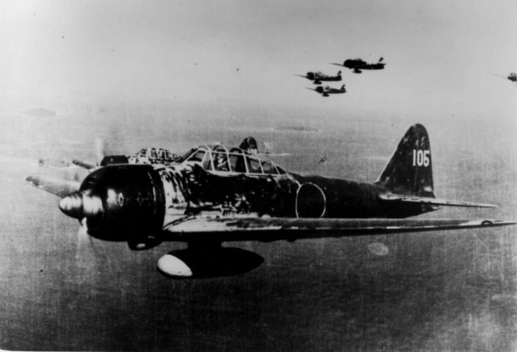
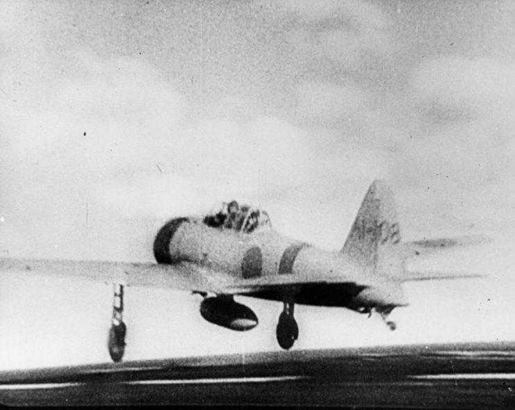
A6M3 Model 22 Zero fighters.
The fighting that took place around Darwin was often hard fought. Capt. Robert Morrissey shot down a Zero, as did his wingman Lt. House. House, whose guns had jammed, saw that his leader was in trouble with a Zero and proceeded to ram the enemy plane. The Zero crashed and the P-40, even though damaged, managed to return to base, albeit with difficulty and a hair-raising landing.
P-40B, X-804 in flight.
The battle on the 14th of March had ended with five enemy planes shot down with the loss of only one P-40, but several others had been heavily damaged and this effectively removed the 7th PS from service until repairs could be made.
1st Japanese attack on Darwin with MV Neptuna explosion. HMAS Deloraine is in the foreground undamaged.
On the 22nd of March, a Japanese Ki-15 Recon plane was sighted and four P-40’s were sent to deal with it. Two pilots engaged the aircraft and it was sent down. They decided to flip a coin to see who would get the kill. It went to Lt. Steven “Polly” Poleschuk. This ended up being his only kill of the war. A large battle on the 31st of March saw P-40s engaging Betty bombers and Zeroes.
Mitsubishi A6M2 “Zero”
Final kill figures for the battle have been debated. At the time, nine kills were credited, but now it’s believed to be only four or five. Either way, it was a good day for the P-40 pilots, with Andrew Reynolds being credited with two kills.

This was enough to make him an Ace with five and a half kills. The day was marred, however, by another friendly fire incident; J Livingstone and Grover Gardner were hit returning to base. Gardner bailed safely from his fighter, but Livingstone was killed.

Attack’s Intensify

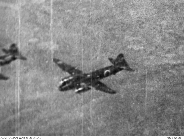
Japanese “Betty” bomber near Darwin.
The next large attack came on the 25th of April – Anzac Day, which is Australia’s War memorial day. On that day, fifty P-40s would take to the air to meet the attackers. Jim Morehead, who had flown in the Java campaign, was credited with three kills – added to his current two this was enough to make him an Ace. The 8th PS was credited with eleven kills from the engagement and the 7th PS with a single Zero shot down by Bill Hennon.

Between this raid and one soon after, the P-40 losses were four with two pilots killed and two wounded. The Japanese attacked from the 13th-16th June and lost fifteen aircraft, while the Allies lost nine P-40s, but only one pilot killed.
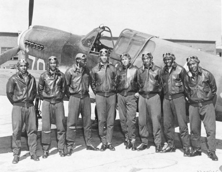
Eight Tuskegee Airmen in front of a P-40 fighter aircraft.
During July, the Japanese started to bomb at night and with the fighting in New Guinea drawing more resources from the Japanese military, the focus on Darwin started to lessen. Andy Reynolds would add another to his tally, giving him 9.3, and Jack Donalson, who had flown in the Philippines, shot down a Zero to give him five kills and Ace status. By the end of the Darwin campaign, seventy-eight enemy aircraft had gone down to P-40 pilots.

The P-40 New Guinea Campaign

Map of Eastern New Guinea.
The 11th of March saw the invasion of New Guinea by Japanese forces. Its location was vital. If the Japanese could take it, then they were in a strong position for launching an invasion of Australia.
Allied ground troops were making a strong fight of it though and the Japanese advance was anything but easy. No 75 Squadron of the Royal Australian Air Force (RAAF) was fighting tooth and nail over the skies of Port Moresby.
Jackson Airfield with B-17s. The field was named after Australian P-40 pilot, John Francis Jackson who was shot down in 1942.
For forty-four days the Australians made the skies very unfriendly for the Japanese pilots. On the 25th of April, the Aussies got some reinforcements in the form of US P-39s and P-40s.
Curtiss P-40 Warhawk on Guadalcanal.
Bill Hennon of the 7th Fighter Squadron also arrived on the 14th of September and started to fly operations almost immediately. The 1st of November saw P-40s clashing with Zeros. After an initial attack, which sent one P-40 down, the rest made a fight of it. Dick Dennis was credited with a Zero kill, as was Bill Day. Day would get Ace status before being lost in action.

On the 22 November, the 7th FS scored two kills while also losing two P-40s, with one of the pilots killed. They again engaged the enemy on November 30th while providing escort. The Zeros got in a good initial attack which destroyed two P-40’s and killed both pilots, but in the fight that followed, the Japanese lost several of their number with no more Allied losses.
Mitsubishi A6M3 Zero wreck abandoned at Munda Airfield, Central Solomons, 1943.
The 7th December 1942 was a good day for the P-40 pilots and the land battle was not going well for the Japanese. They sent a large bomber force to attack allied ground forces. This force was met by the 7th FS and Frank Nichols scored a kill with a head-on pass.
Japanese cruiser Haguro and cargo ships under attack at Rabaul.
A second bomber was lost and the remaining aircraft ditched their bombs and turned for home. Unfortunately for them, they were met by eight fighters of the 9th FS, led by Bob Vaught, a veteran of both the Java and Darwin campaigns. He pressed the attack in his fighter, nicknamed “Bobs Robin,” and got two kills (his 2nd and 3rd).

More bombers fell to the P-40s before the bomber escorts were in a position to engage. The P-40s then disengaged from the fight and were more than happy with the outcome. On the 26th December, the Japanese attacked Dobodura and engaged some RAAF Hudsons that were trying to land.
A Hudson Mk V.
Luckily the 9th FS was already airborne and could attack the Ki-43 Oscars. Five P-40s claimed single kills during the battle. During the battle, John Landers found himself in the unpleasant position of being alone with six Oscars. He managed to down two of them before his P-40 was fatally hit and he was forced to bail out. He was met on the ground by natives. With the two kills, it took his tally to six and Ace status.

Re-equipping Fighter Squadrons

As 1943 came, the pressure was being applied to the Japanese forces, who had now taken on a defensive position. The 9th FS would trade in their P-40s for the remarkable twin-engine P-38 Lightning. One unusual mission required the P-40s to bomb a Japanese convoy, not something the pilots had any experience doing, and only one ship, the Myoko Maru was hit. While damaged, it still managed to reach the safety of port.
Squadron Leader and Ace Turnbull – New Guinea 1942.
The 49th FG moved closer to the front line, which gave them more time on target, but also aroused the interest of Japanese bombers. A large battle erupted on the 11th of April which resulted in two Val dive bombers being destroyed by the 7th FS and 7 by the 8th FS. Ernie Harries got three kills which took him to seven kills and Ace.

A further five enemy aircraft were shot down on the 12th of April. On the 14th of May, a large force of enemy aircraft targeted the airbase at Dobodura and the nearby docks. Around fifty aircraft took part in the attack; a mix of Betty Bombers and Zero fighters. The P-38s of the 9th FS were already harassing the Japanese formations as the P-40s arrived. When it was over, the 7th FS had destroyed five and the 8th an amazing thirteen.
The U.S. Army Air Forces Curtiss P-40L Warhawk.
Considering the P-40 was inferior to many of its opponents, the pilots and support crews had done an amazing job. The 7th and 8th FS had destroyed eighty-seven enemy aircraft at a loss of just five pilots killed in action. They were really hoping for P-38s when news came down that they were going to be re-equipped. In the end, they got the latest mark of P-40 and while it was an improvement it didn’t make many pilots happy.
Australian pilots with a P-40 Tomahawk.
Only the 35th FS/8th FG was excited about it. They had been flying P-39 Airacobras and they disliked them immensely. They had a total of twenty-three kills from April 1942 and had only managed one kill during the first six months of 1943. With their new mounts, they destroyed three Betty bombers and a single Ki-61 Tony fighter on the 6th of September.

On the 22nd they would get seven kills. When the 2nd of January 1944 came, the 35th got involved in a battle with forty enemy aircraft. They shot down nineteen; Bill Gardner and Lynn Witt Jr had three kills apiece; Bud Pool had two kills and Lee Everhart’s two kills gave him a total of five and Ace. In February 1944, the 35th re-equipped with P-38s.
P-40s in formation 1941.
For their time in P-40s, they had a total of sixty-five confirmed kills. The 7th and 8th FS had continued to fight on with several pilots reaching the status of Ace. Jim Hagerstrom with six kills, Arland Stanton with five kills, and Bob DeHaven and Ernie Harris both had ten kills.
Wilfred ‘Woof Arthur was credited with 10 kills during WWII.

Warhawk becomes a Legend

The P-40 wasn’t the best fighter in the Pacific and it wasn’t the sexiest, but it was in harm’s way when nothing else was available and stayed in service longer than it should have.
Curtiss P-40E
Yet in the hands of a skilled and determined pilot and a great ground crew, the P-40 could beat anything that the Japanese sent against it.

Meet the Aquatic Drone Saving the Great Barrier Reef with Machine Learning and Computer Vision

$
0
0
The Queensland University of Technology has announced that its robotic hunter-killer aquatic drone will now double as a seaborne midwife to save the Great Barrier Reef.

Underwater drones are finding more applications for ocean conversation. One of the most famous underwater drones is the RangerBot from the Queensland University of Technology (QUT) in Australia. This is an underwater drone that, according to its developer, Professor Matthew Dunbabin, “is the world's first underwater robotic system designed specifically for coral reef environments, using only robot-vision for real-time navigation, obstacle avoidance and complex science missions.”

The device, which won the 2016 Google Impact Challenge People’s Choice prize, employs multiple thrusters for locomotion, as well as computer vision and machine learning for obstacle avoidance and real-time navigation. A surface-based human can operate the 15kg, 75cm long RangerBot via a simple tablet-based controller.


The RangerBot. Image used courtesy of Great Barrier Reef Foundation

In a collaboration funded by the Great Barrier Reef Foundation, QUT’s Professor Dunbabin and Professor Peter Harrison of Southern Cross University (SCU), RangerBot’s capabilities will be utilized to restore damaged areas of Australia’s Great Barrier Reef.

RangerBot's Computer Vision

RangerBot's vision system comes largely from the research of QUT's Dr. Feras Dayoub. His 2016 paper in IEEE's Proceedings of the International Conference on Robotics and Automation was titled "Place categorization and semantic mapping on a mobile robot"—pretty clearly of enormous importance to RangerBot's ability to interpret visual data.

His most recent publication is "A rapidly deployable classification system using visual data for the application of precision weed management", a paper that has obvious possible future applications for classifying species of coral.

In RangerBot's and COTSbot's case, computer vision has proved key for identifying crown-of-thorns starfish:


COTSbot's computer vision at work. Image used courtesy of QUT

RangerBot Responds to the Starfish Threat

The RangerBot derives from the earlier COTSbot, also developed at QUT, which was aimed at eliminating the lethal threat to coral reefs posed by crown-of-thorns starfish infestation (hence "COTS" for "crown-of-thorns starfish"). Previously, all efforts at control were through the efforts of human divers.

The comparison below from the Great Barrier Reef Foundation tells the story:

Human divers vs. RangerBot. Image source (modified): Great Barrier Reef Foundation

Divers are limited to three hours a day of underwater work, and, of course, the costs of equipping, protecting and deploying divers are quite high. As we can see from the very first line of the comparison, it is estimated that RangerBot can kill starfish over 28 km of coral reef in a single day, as opposed to the 1 km length of the coral reef that can be covered by a human diver.

Additionally, RangerBot can collect vast amounts of data pertaining to the condition of the coral reef.

A look at the electronics inside RangerBot’s predecessor, COTSBot. Screenshot used courtesy of the Australian Museum

But these tasks have not been enough to keep RangerBot in one role. Its new job is more oriented towards nurturing than assassinating starfish. 

Rebirth of a Coral Reef: RangerBot to LarvaBot

Regardless of what killed them, coral reefs can, essentially, be “replanted”. While RangerBot's so far been focused on preventative action and data-gathering, QUT recently announced that it will now put on a new hat where it will promote new reef growth.

Under Professor Harrison’s direction, hundreds of millions of coral spawn are collected and then developed into baby corals or larvae. This allow's Professor Dunbabin’s versatile RangerBot to become LarvaBot, a drone re-tasked with spreading Harrison’s larvae into depleted regions of the coral. And, because the health of the coral reef has already been assayed by previous sojourns of RangerBot, the areas that needs “rebirth” are already well known.


Possible Future Applications: Additional Threats to Coral Reefs

According to the Smithsonian Institute, coral reefs cover less than two percent of the ocean’s bottom but are a crucial factor in the life-cycle about one-quarter of all oceans species—including, presumably, the fish that humans eat. Yet, coral reefs are dying, posing a grave threat food supplies and more.

As described by the Great Barrier Reef Foundation, the greatest threats to reefs are:
  • Climate change leading to ocean acidification
  • Coastal development affecting habitat
  • Illegal fishing and poaching
RangerBot has already tackled hunting crown-of-thorns starfish and now spreading new coral larvae to counteract reef loss. In the future, perhaps QUT will address these other issues, possibly with sensors to measure acidification or new algorithms to identify and track species of coral.

Whatever job RangerBot gets into next, it will certainly be worth watching.

Regular Bugatti Veyron Maintenance Work Is Insanely Complex

$
0
0
And you thought Veyron ownership costs ended when you bought the car.

Chances are you’ve never owned a Bugatti Veyron. If you have and/or still do, first off, congratulations. Second, you’ll totally understand and relate to the ownership complexities specifically involving maintenance. In short, life with a Veyron is very expensive and that doesn’t include regular fill-ups. A regular oil and fluid change will cost around $20,000. That’s not a typo. Of course Bugatti really wants owners to have their Veyrons (and Chirons) maintained at Bugatti dealerships where their highly trained technicians will ensure everything is in order.

But here’s the thing: the Bugatti dealer will slap owners with that hefty bill upon competition of work. If owners don’t go to a certified technician for work, there’s a chance the warranty and other perks will be invalidated. It’s sort of a catch-22. However, as you'll see in the following video, there are Bugatti owners out there with the tools and knowledge required to handle things on their own.


Las Vegas-based exotic car rental firm Royalty Exotics boasts a 37-car fleet of exotics that includes a Mansory-tuned Veyron. Company owner Houston Crosta fortunately has the resources and technical talent in-house to maintain all of his cars, thus allowing money to be saved by avoiding the dealership. The video shows just how complex and potentially time consuming it is just to change a Veyron’s oil and change its fluids. For example, a total of 16 drain plugs need to be removed to change the oil. The work originally started because of a hydraulic leak coming from the rear. The engine cover had to be removed to find the leak. Still want to own a Bugatti? Be sure your bank account remains healthy.


Lamborghini SC18 Is A 770-HP One-Off Track Monster

$
0
0
For the first time ever, Lamborghini’s Squadra Corse motorsport division has released a one-off, Aventador-based track day beast of its own, the SC18. It wasn’t built for any old reason but rather for a wealthy customer who helped design the car “in synergy” with the Italian supercar company. Now, Lamborghini designers and engineers have been known to be, shall we say, the mad scientists of supercar concepts over the years, and the SC18 is certainly no different. Let’s talk some details.

The naturally aspirated 6.5-liter V12 produces a wonderfully ridiculous 770 hp at 8,500 rpm and 531 lb-ft of torque, with all of that power distributed to the four wheels through a seven-speed gearbox. Lamborghini did not reveal any performance specs but it’s not hard to imagine this thing is wicked fast.


Its owner requested extreme aerodynamics, all of which were specifically developed for the car and were derived from Squadra Corse’s competition experience. The front hood features air intakes in the style of the Huracan GT3 EVO while the sides and rear feature fenders, fins and air scoops inspired by the Huracan Super Trofeo EVO. A large carbon fiber wing with three mechanical adjustments is capable of generating optimal downforce. The 12 air intakes formed on the hood also increase heat exchange and improve cooling for the V12. Out back you’ll find special exhausts and terminals with a unique design and sound.

Like the Aventador, the SC18 isn’t exactly tiny but Lamborghini worked to offset the car’s size and bulk and, therefore, weight, with a lightweight carbon fiber body, painted in Grigio (grey) Daytona with red trim.

Wheel sizes are staggered with 20-inch up front and 21-inch at the rear wearing Pirelli P Zero Corsa tires. The interior is done in Nero Ade (black) Alcantara with cross-stitching in Rosso Alala (red) and carbon fiber bucket seats. Unfortunately, because the SC18 is a one-off build for a private customer, we may never know, or let alone see, all of its true track capabilities. Enjoy looking at it now because we may not see it again. Pricing, not unexpectedly, was not announced.


First 2019 Ford GT Heritage Edition Is Up For Grabs

$
0
0
Proceeds from retro-themed supercar's auction will go to charity.


Eager to get your driving gloves on a new Ford GT, but not so keen to fight for a spot on the waiting list? Your rare chance is coming up in January when Barrett-Jackson will auction one off to the highest bidder.

And it's not just any Ford GT, either: the car in question will be the very first 2019 Ford GT Heritage Edition, decked out in classic Gulf Oil livery, with VIN 001. And to make the prospect even more enticing to prospective bidders, the proceeds from the sale – which are sure to be quite substantial – will go to charity.


The Heritage Edition pays homage to the GT40 that won the 24 Hours of Le Mans half a century ago in these very same colors. The optional appearance package for the Blue Oval supercar applies an orange nose and central stripe over baby-blue bodywork, with orange brake calipers to match inside 20-inch dark gloss alloys. It also features silver mirror caps, exposed-carbon A-pillars, and a cabin all wrapped in black Alcantara with blue and orange stitching and matte carbon interior trim. Ford even updated the original number 9 with a more contemporary graphic better suited to the modern supercar.


The car will be auctioned off in Scottsdale, Arizona, on January 19, with proceeds benefiting the United Way for Southeastern Michigan. But even if you miss out on this one, the same Barrett-Jackson event will also feature seven 2005-06 Ford GTs, including three similarly liveried Heritage Editions.

“The 2019 Ford GT Heritage Edition instantly became one of the most anticipated cars in the world with its famous paint scheme,” said Ford's Joe Hinrichs. “This car’s amazing history should help the United Way for Southeastern Michigan raise a lot of money to advance their mission of helping make lives better in our communities.”


Is This The Most Complex Wheel Design Ever?

$
0
0
3D-printed titanium design is a world first.


One of the easier modifications you can perform on your car is to swap out the factory-installed wheels for a set of four aftermarket rims. While it's definitely possible to overdo it with oversized or tasteless design, a clean set of custom wheels can add a nice personalized touch to your vehicle.

If you're currently searching for new wheels and want to set yourself apart from the pack, you may be in luck. HRE Wheels has paired with GE Additive (a subset of General Electric) to create the first 3D-printed titanium wheels, the HRE3D+, sporting a fiendishly elaborate, artistic design.


Part of what makes the HRE3D+ so jaw-dropping is the layering effect, which sees several different spoke designs seemingly intertwined with each other. The visual complexity is achieved by creating the wheel in five separate sections—all 3D-printed—before connecting them via a custom center section. This structure is then secured to a carbon fiber rim by titanium fasteners.

Along with this layering effect, the 3D-printing process allows for the intricate latticework that has been chiseled into the HRE3D+’s titanium spokes. These elements combine to create an appearance that is reminiscent of the mechanical artistry found inside of high-end luxury watches.


The 3D-printing process was not just utilized simply for the aesthetic freedom it allows—there are functional benefits as well. When crafting a traditional aluminum “Monoblock” wheel, it begins life as a 100 pound forged block of aluminum before having 80 percent of its material carved out to produce the final design. This is highly wasteful: HRE and GE’s new method is vastly more efficient.

By utilizing a process know as additive manufacturing, only 5 percent of material is wasted by removal. Using titanium also brings benefits—the metal has a far higher specific strength than aluminum and is resistant to corrosion. This permits the wheel to be extremely lightweight and allows HRE to display the design in its raw finish.

HRE has shown off its new wheels on a stunning McLaren P1, but we imagine they would look equally hot on a 720S. While the 3D-printing technology and additive manufacturing technique may restrict these designs to the upper echelon of customers for the foreseeable future, as the costs of these methods decrease over the next few years, look for these intricate designs to spread throughout the custom wheel market.


Bosch Introduces Position Tracking Smart Sensor as Part of Third Wave of Sensor Technologies

$
0
0
Position tracking of a device can be a power-intensive task, especially when trying to maintain accuracy. While GPS is a highly accurate solution, it tends to fail when the device is too close to buildings or tunnels, and has a fairly high power requirement. Other options, like Inertial Measurement Unit (IMU), are less power demanding but tend to drift in accuracy over time when used alone.

In what it refers to as its "third wave" of intelligent MEMs sensor technologies, Bosch has recently announced the BHI160BP—a lightweight, small form factor, and low power consumption position tracking sensor.

The BHI160BP features an integrated three-axis accelerometer, a three-axis gyroscope, and a programmable microcontroller that can be paired with an absolute positioning device, such as GPS, for position tracking.

Image courtesy of Bosch.

Low-Power Position Tracking

What makes this sensor unique is that the GPS is duty power cycled—in between GPS position reporting, the other inertial sensors interpolate the current position using a Pedestrian Dead Reckoning (PDR) algorithm. This combination reduces the power requirements of an "always on" position tracking system, while maintaining near-absolute positioning. Bosch says this allows 80% less power consumption than an always-on GPS sensor. The sensor is also reliable in environments where GPS tracking may typically fail, both indoors and outdoors.

Bosch envisions the sensor as being used in small devices such as wearables and other small devices where battery power may be limited, and in applications that require robust position tracking. Further, the sensor is also capable of withstanding mechanical stress.

The BHI160BP microcontroller also comes with other available algorithms and software to allow features such as 3D orientation and wake-up on wearing easily available. A Sensor-API and PDR-GNSS fusion library are also available to make integration easier.

BHI160BP Specs

  • Dimensions: 3.0x3.0x0.95 mm3
  • Power consumption: Six typical profiles ranging from 11 μA (suspend mode) to 1.3 mA (6 degrees-of-freedom PDR)
  • Typical PDR power savings: 80%
  • Position accuracy: 10%
  • Step counting error: 5%
  • Primary host interface: I2C, 3.4M Hz

Image courtesy of Bosch.

Pedestrian Dead Reckoning (PDR)

Dead reckoning is a method of determining position using information about current speed, known distance traversed, and last known position. It has been applied and used in air navigation, sea navigation, and even among animals. On ships, compass headings and time were used to calculate position when navigating through foggy or dark waters.

The challenge with dead reckoning in wearable or smartphone devices is that there is a complex range of motions and orientations associated with its use. Whether it a smartwatch on the wrist of a swinging arm, or a smartphone haphazardly thrown into a pocket, these present slightly more complex challenges in calculating the magnitude and orientation of movement.

That’s where Pedestrian Dead Reckoning comes in. A variety of sensors provide information on orientation, acceleration, and inertia; algorithms can then detect movement patterns such as walking or arm swinging and separate out that information to make dead reckoning calculations.

The Third Wave of MEMS Sensors

If this is the third wave of Bosch MEMS sensors, what were the other two?
Bosch perceives the evolution of its MEMS sensors as waves:
  1. First wave: Automotive sensors in the 1990s (airbags for safety, engine management, etc.)
  2. Second wave: Consumer electronics in the late aughts, early 2010s (particularly cell phones but also including drones, etc.)
  3. Third wave: IoT, beginning in the 2010s (including smart homes, industry, etc.) 
This new sensor is part of the third wave because it's an example of what they refer to as localized intelligence.

A Magical Application: Bringing the Marauder’s Map to Life

For those not familiar with the fantasy world of Harry Potter, the Marauder's Map is a map that can display the exact location of individuals inside Hogwarts castle. While the Marauder's Map is powered by magic in the novels, in real life, precisely tracking the position of individuals within the stone walls of a castle would pose challenges due to poor GPS reception.

Bosch explores the possibility of bringing the Marauder's Map to life using the BHI160BP sensor: if the individuals within the castle are wearing smart watches or have smartphones with the sensor available, which then transmits its location to receivers, live tracking can be performed to show location and speed of individuals within Hogwarts castle without requiring a constant GPS fix.

If anything should inspire you, the idea of creating magical objects using today’s technology may certainly be motivating.

As Emerging Technologies Outpace Semiconductor Processes, IBM Takes Leap Towards 7nm IC Fabrication

$
0
0
Traditional IC manufacturing methods can't keep up with industry demands for long. IBM researchers are looking to nanofabrication of ICs for the next generation of semiconductors.
IBM has developed several new materials that make selectively depositing materials on features as small as 15nm.

The methods involved are described in a paper published in Applied Materials & Interfaces by an IBM team headed up by Rudy Wojtecki. Traditional fabrication methods involving coating, patterning, and stripping can be bypassed through the use of what's called selective area atomic layer deposition or SA-ALD.

While the employment of selective deposition isn’t revolutionary, several new self-assembled monolayers (SAMs) developed at IBM now make it possible for selective deposition to be applied at a scale tiny enough to be relevant for building state-of-the-art semiconductors.

Selected Area Atomic Layer Deposition

The method described in the IBM paper involves selectively depositing material on areas as small as 15nm by growing a film on a selected area, as illustrated by the blue “Material 2” in the illustration below.


SA-ALD illustrated. Reprinted (adapted) with permission from ACS Appl. Mater. Interfaces 2018, 10(44), pp 38630-38637. Copyright (2018) American Chemical Society.

As Rudy tells it in an article he wrote for IBM, “Enabling fabrication beyond 7nm”, “With traditional methods of fabrication, this would require coating a substrate with resist, patterning the resist through an exposure step, developing the image, depositing an inorganic film and then stripping the resist to give you a patterned inorganic material. We found a way of depositing this inorganic film much more simply, using a self-aligned process.”

In the image above, the Material 1 areas are “blocked”, so atomic layer deposition only takes place in the center on Material 2.

The ALD film can serve as a target for the further building up of a chip, thus enabling self-alignment, especially critical on the tiny scale of 7nm. Imagine if a chip were like a street grid, with one layer being the streets, and another layer, perpendicular to the streets being the avenues.
Even if the methods of fabricating the streets and avenues were both satisfactory, if they don’t line up correctly with respect to each other, all is for naught. Self-alignment belays that risk.


This scanning electron micrograph shows selectively deposited film at different magnifications and includes an inset of pre-patterned tungsten with areas containing inhibitory molecules shown in blue. Image from IBM

In essence, these researchers are working towards the ability to reliably grow nanoscale components.

IBM’s New Self-Assembled Monolayers (SAMs)

IBM has gone beyond the off-the-shelf reagents and is developing new SAM components that make this development practicable. They are:
  1. Octadecyl phosphoric acid
  2. Urea-containing component
  3. Aromatic component
  4. Photoreactive diyne component

The SAM component that enables IBM’s new method. Reprinted (adapted) with permission from ACS Appl. Mater. Interfaces 2018, 10(44), pp 38630-38637. Copyright (2018) American Chemical Society.s

Moore’s Law Finally Overturned?

There’s little doubt that the number of transistors that can be loaded on an IC won’t be doubling every two years anymore. As Rudy describes in his blog, “current semiconductor fabrication processes are nearing fundamental limits, and the emergence of AI is driving demand for non-traditional computing architectures, new methods to fabricate at the nanoscale are required.”

Indeed, the radius of the hydrogen atom itself is about 0.1 nanometers, only about 100 times the dimensions being discussed in the Applied Materials & Interfaces article. There isn’t much further to go, and every step forward from now on for investigators like Rudy Wojtecki and for groundbreaking organizations like IBM will be more difficult than the last.


Featured image adapted from IBM

Newest Dialog Semiconductor PMIC Tackles Big IoT Design Issue: Extending Battery Life for Wearables

$
0
0
Dialog Semiconductor's newest PMIC (power management IC) aims to help solve the battery life issue for wearables and other small, portable applications—a now-familiar challenge for many IoT device designers.

Last week, Dialog Semiconductor released their latest PMIC designed to manage power for IoT devices that need to extend their battery life (presumably most of them).

To learn more, AAC spoke with Faisal Ahmad, Dialog Semiconductor's Director of Marketing for their power management and audio products within mobile systems business unit.
Here's a look at this IC's most important features, the significance of fuel gauges in wearables, and where the wearables market is going.

Power Management for Small IoT Applications

The DA9070 is a nanopowered PMIC designed to power IoT equipment. One of the major focuses of this product is wearables such as fitness trackers, but IoT here could also mean smart home or building automation applications or even key fobs.

The goal is to extend the life of small batteries, especially in those applications where there's some kind of always-on functionality (say, a sensor for home automation or a clock for a wearable).
This chip consumes very low quiescent current while maintaining voltage regulation required by the components in the system.

To accomplish this, the DA9070 features the following components:
  • Battery charger for rechargeable battery
  • Buck regulator to power the system's MCU
  • Boost regulator to power display or high-voltage sensor
  • Three linear regulators to power other I/Os or sensors
  • Analog battery monitor to create a fuel gauge for the device 


Block diagram for the DA9070. Click to enlarge

A Low-Power Fuel Gauge

This last feature, the fuel gauge, is an important one. Oftentimes, small IoT devices have a bar indicator for gauging how much battery remains (e.g., three bars indicates ~75% battery life remaining where two bars indicates ~50%). Ahmad says this is because fuel gauges generally consume a lot of current, draining the battery that they're measuring.

"Our fuel gauge only consumes 4μA and actually runs in the system MCU so it's very low-cost," he says. "It takes voltage and current information from our PMIC and creates the fuel gauge."


The fuel gauge interface

Use this gauge functionality is eased by software available of Dialog's website, including "a full set of software that walks you through the process of creating a fuel gauge."

The DA9070 Dev Board

The DA9070 has a dev board for designers to work with. The board comes with a 80mA hour battery, a common size for, say, a fitness tracker. In addition to the PMIC there's also included a typical MCU (an m4 ARM Cortex core) loaded with Dialog Semiconductor firmware to measure voltage and current and to run the algorithm to create fuel gauge.


The DA9070 dev board

An Integrated Solution with Some Flexibility

Problems with small designs often require solutions with small footprints. As Ahmad puts it, "We're solving the problem with a highly integrated solution because many of these systems are very small."
While this level integration is important for this particular PMIC, according to Ahmad, it's also "flexible enough where various regulators can be used for different circuits" depending on what's going on in the system.

"This part is perfect for someone who's got the challenge of trying to fit their circuity in a small space and make their battery last as long as possible," he says. "Every component of the device is really tuned for optimizing battery life. Everything can also be controlled digitally through an I2C interface so—if you're a system designer who's got more of a background in embedded design, writing code into an MCU—it makes it really easy to control the device with the driver we provide and control everything digitally."

Dialog Semiconductor and the Future of the IoT

Ahmad believes that the wearables market is still relatively new. It's only been a handful of years, he points out, that we've been able to acquire fitness trackers in major stores. In the coming years, he thinks that wrist wearables may consolidate some. "But," he says, "we're still seeing a lot of innovation and new ideas for just wearables other than [those that are worn on the] wrist." Indeed, the wearables umbrella is widening, including jewelry like rings and pendants, shoes, and even textiles straight into clothes.

One of the reasons that the wearables market is likely to continue to grow, Ahmad says, is that "generally speaking, one of the main driving forces of having wearables is improving your health. That's a big market. It should be a priority for most people. If you're helping do that, there will always be an opportunity there."

For Dialog Semiconductor, this is good news. "We do see [the IoT space] growing. In general, for our power management, we're all about efficiency and extending battery life," Ahmad says. "And this is a market in which that's the big problem—so it's a great fit for us from a technology perspective."


What challenges have you come across when trying to power small IoT devices? What methods have you used to try to solve them? Let us know in the comments below.

Utilizing the Different Types of Common IoT Connection Methods

$
0
0
This article explores the pros and cons of connectivity options for IoT edge device design, discussing the importance of putting the I in IoT.

If you’re reading this article online, odds are you are connected over cellular, Wi-Fi, or Ethernet. While these connectivity methods are widespread in consumer electronics, Internet of Things (IoT) edge nodes aren’t as tied to them. Unlike consumers, most edge devices do not check email (lucky them) or indulge in streaming movies, so they do not require the high data rates used in consumer electronics.

IoT solutions often consist of hundreds, or thousands, of connected edge devices. Typical design constraints, such as cost and power management, become magnified as more edge devices are added. At that scale, the way your product connects to the internet can determine whether it succeeds or fails.

The Internet of Things (IoT) is made up of up of hundreds, or thousands, of devices connected to the same network
Figure 1. The Internet of Things (IoT) is made up of up of hundreds, or thousands, of devices connected to the same network.

This guide will give you an overview of the most common types of connection methods utilized in IoT applications. Follow along to weigh your options and determine how you want to put the ‘I’ in your IoT design.

Ethernet

Ethernet is a fast and reliable way to connect things to the internet. Commonly found in industrial and building automation, Ethernet shines in systems that include many nodes on the same network.
Because Ethernet is hardwired, it is also inherently a very secure connectivity method. There is also the capability to power your device through the Ethernet cable through Power Over Ethernet (PoE), which eliminates the need for a separate power module.

Hardwiring does, however, present significant design challenges, and certainly does not make sense for every application. Nodes connected by Ethernet must be close to a router. Even in short distance applications, such as home and building automation, Ethernet cabling is so bulky that managing and hiding the wires presents a major challenge. In modern buildings, automated lighting systems are hardwired during construction, but installing an Ethernet IoT system in a building not designed for it is often not feasible.

Wi-Fi

As the go-to for internet connection, the wireless nature of Wi-Fi is incredibly appealing. It is widely supported by mainstream devices and does not contain the hardwiring constraints of Ethernet.

Despite its prevalence, adding Wi-Fi capability to an embedded design is typically complex. Wi-Fi is attractive because it is wireless and fast, but those features come at the expense of security vulnerabilities and power consumption. As a result, Wi-Fi-based IoT designs require an engineer to delicately balance security, power, and cost.

A favored internet connection option in consumer electronics, Wi-Fi brings the benefits of high-speeds and wireless connection
Figure 2. A favored internet connection option in consumer electronics, Wi-Fi brings the benefits of high-speeds and wireless connection.

Luckily, solutions exist today to help engineers overcome these barriers. Using a Wi-Fi module that has been optimized for IoT will simplify your design and save development time. Modules like the WINC1500 are fully certified, support security protocols and are optimized for battery-powered devices, enabling Wi-Fi connectivity without compromising on cost and power consumption.

Low Power Wide Area Network (LPWAN)

LPWANs are less common in consumer products, so you may not be as familiar with them. A significant portion of IoT applications are in wide-area applications, such as environmental monitoring.

The beauty of using IoT for environmental monitoring is that we can monitor rural, offshore and generally inaccessible areas. The issue is that these locations are rural, offshore and generally inaccessible. You cannot give a device floating in the Mariana Trench a quick recharge or connect to Wi-Fi in the Mojave Desert.

Agriculture is a perfect application of LPWANs because these networks can cover large swaths of area with very little power
Figure 3. Agriculture is a perfect application of LPWANs because these networks can cover large swaths of area with very little power.

Ranges in typical LPWAN use appear to hover around 10 kilometers (km). Data is transferred at very slow rates, but unless your IoT solution is checking email and streaming videos, you probably will not need a high-speed connection.

While commonly used in agricultural and remote applications, LPWANs aren’t exclusive to them. Urban usage is growing, and one of the largest LPWAN commercial IoT deployments in North America is used to track vehicles in auction lots.

There are two common LPWAN protocols: LoRaWAN™ (from Long Range, or LoRa®) and Sigfox. One difference between the two is cost. Sigfox is a subscription-based service and operates similarly to cellular. If Sigfox is available in your area, you can connect through a subscription with a local provider. With LoRaWAN, developers can avoid a subscription fee by creating a “do-it-yourself” network, but most still opt to use a local network provider’s LoRa gateway infrastructure and pay a per-usage fee. 

Cellular

Aside from extremely rural and remote areas, cellular coverage blankets the world. For embedded systems that need this range, cellular is the only option. However, it is expensive. You must use a provider, and you cannot set up your own network without governmental regulatory approval. The cost of the embedded components and provider subscriptions for each node often outweigh the benefits of cellular networks’ extensive reach.

That said, it is important to distinguish the cellular network used for connecting things and the bill you cough up once a month for your phone. IoT-specific cellular networks are popping up to compete with LPWANs. A growing IoT Cellular network is LTE CAT-M. The M stands for “machine,” and it is a lower speed, lower cost, lower power option optimized for IoT. While your cell bill might be substantial, a CAT-M plan runs around $7/month for 5 MB of data. Other options for cellular IoT connections are CAT-0, CAT-1 and the newer NB-IoT (NB for “Narrow Band”).

As 5G rolls out, we can expect it to drive innovation in IoT. The higher speeds of 5G could enable more progress in cutting-edge IoT applications, such as autonomous vehicles, albeit at a higher price tag than IoT-targeted networks. 5G coverage is not nearly as pervasive as LTE or 3G, but it is expanding. Some industry analysts have predicted that 5G will reach up to 20 percent of the world’s population in the next five years.

Satellite

Cell coverage might blanket most of the populated world, but what if you want to connect things in spread-out, desolate areas?

Satellite connectivity is used for IoT applications such as shipping logistics in remote regions of the Earth that are not covered by cellular service. While expected to change as satellite technology progresses, developing a satellite IoT application is not as accessible as other connectivity options. Many satellite constellations are reserved for defense use, but you can purchase modules from Iridium® and ORBCOMM®. 

While satellite is beneficial for remote areas of the world that are not covered by cell service, options are currently limited for commercial IoT use
Figure 4. While satellite is beneficial for remote areas of the world that are not covered by cell service, options are currently limited for commercial IoT use.

Bluetooth

You’re probably also already familiar with Bluetooth. Both Bluetooth Classic and Bluetooth Low Energy (BLE) have max ranges exceeding 100 meters but are typically used for devices that are within a few meters of each other. In our daily lives, we see Bluetooth in accessories for our phone and PC – headphones, keyboards and display technology.

Bluetooth is great for consumer electronics because it is low power (with BLE being exceptionally low power), widely supported and pairs quickly.

Unlike Wi-Fi, Bluetooth does not directly connect to the Internet. You will need to set up a gateway to connect to the internet. While setting up your own gateway may seem daunting, it’s often as easy as connecting to a mobile device that also connects to Wi-Fi.

Bluetooth 5.0 is a recent update that extends Bluetooth’s range so that it can be used in home area networking. Whereas Bluetooth Classic and Bluetooth LE are typically used to connect devices that are mere meters apart, you can connect an entire home with Bluetooth 5.0. This extended range brings Bluetooth into the realm of home automation, lighting, and industrial applications.

Implementation Recommendations

A major way these connectivity methods vary is in ease of implementation. Commonly used networks, such as Wi-Fi and Bluetooth, are often the easiest way to evaluate and explore IoT designs. These networks do not require you to build your own gateway or pay for a provider.

Several Wi-Fi and Bluetooth prototyping modules are available to consumers, and many come with open source code and tutorials on how to program them. Using connectivity modules is recommended because it makes the design more flexible. When it comes time to adapt your design for a different network, you can swap out the module instead of starting from scratch.

Easing the Design Process

Connecting to the internet is just one component of IoT design. IoT systems should check three boxes: smart, connected and secure.

This translates to three electrical components: a microcontroller (MCU), a connection module and a secure element. The challenge of IoT design comes from the integration of these three components.
Microchip’s AVR-IoT WG development board is an example of a streamlined Wi-Fi development platform. The board is preconfigured to securely connect to Google Cloud’s IoT platform. With a secure element, Wi-Fi controller and an MCU all on one board, you can skip much of the nitty-gritty design work and get to what matters: innovating and taking your IoT product to market faster.

The AVR-IoT WG development board is pre-configured to securely connect to Google Cloud
Figure 5. The AVR-IoT WG development board is pre-configured to securely connect to Google Cloud.

The Arduino Uno WiFi Rev 2 also offers smart, connected and secure elements. Arduino hosts an active prototyping community with many tutorials and open source code available online.

MikroElektronika click boards™ are rapid-prototyping modules that connect directly to the AVR-IoT WG development board, or through a shield for the Arduino Uno WiFi Rev 2. With several connectivity click boards available, including a variety of LoRa and Bluetooth modules, these boards offer a great way to add connectivity to your IoT design during the prototyping phase.

The MikroElektronika BLE2 click board integrates easily into many general-purpose development platforms
Figure 6. The MikroElektronika BLE2 click board integrates easily into many general-purpose development platforms.


Through user-friendly tools such as Arduino and the AVR-IoT WG development board, building an IoT device has never been more approachable. Whether you’re an embedded designer by profession, a maker or just a devoutly curious electronics blog follower, you’re capable of building an IoT network. This powerful accessibility, coupled with an increasingly connected world, ensures that connectivity will continue to drive progress in an unprecedented way.

An EV Made to Demo Motion Control: Monolithic Power Systems’ mCar Shows Off Angular Sensors

$
0
0
Monolithic Power Systems wants to give optical encoders a run for their money. The MPS mCar EV demo showed off angle position sensors and motion control at electronica 2018.

At electronica 2018, there were several automotive-centric demos at booths, sometimes even displays of ritzy F1 cars sponsored by electronics companies. Among these was a uniquely non-automotive-focused display: an electric vehicle designed specifically to demonstrate motion control and angular sensors.

Monolithic Power Systems is not necessarily the first company that comes to mind when you think of EVs, particularly not in the veritable sea of EV announcements and automotive-related products at electronica or other popular shows. Yet there sat the mCar, MPS's demo at their booth, an undeniably interesting electric vehicle with pivoting wheels slowly inching across the showroom floor.


The mCar roaming free in MPS's demo video

MPS mechanical engineer and primary designer of the mCar Aaron Quitugua-Flores explains that the mCar is the brainchild of CEO Michael Hsing. Hsing reportedly loves vehicles and determined that a custom EV would be an attention-grabber for MPS. The issue, of course, was that MPS didn't have the required machine shop to develop such a project.

So, quite simply, Quitugua-Flores was hired to build one.

Over the last year and a half, a team built a machine shop in San Jose and designed, fabricated, and created the electronics integration for the mCar, in partnership with a China-based team that handled the motor control aspects.

The mCar, overall, represents a hugely ambitious project to develop an EV to demo products that don't necessarily have EVs in mind.


The mCar doing donuts with its tires pivoted inward in the MPS video

So if MPS isn't what comes to mind when one thinks of automotive, how did the mCar fit into electronica? MPS is no stranger to power-related components, infotainment systems, and lighting in automotive, but nothing on what Quitugua-Flores calls a "macro-scale."

"We've had several people ask, I assume semi-jokingly, 'Can we buy the car?'" he says. "And that's part of the reason we wanted to build something like this. We wanted people who don't necessarily know what MPS does to be able to come in and start a conversation."

While MPS isn't trying to sell a car, the mCar shows off several functions that one may need in their own applications. In addition to showing off MPS's core components (power regulators, voltage regulators, voltage converters, etc.) the mCar hopes to demo two main functions:
  • motor control elements
  • angular position sensors

Smart Motor Control Modules

The mCar demonstrates several smart motor modules. These include a BLDC motor coupled with an integrated control module already attached to the motor. "With that," Quitugua-Flores adds, "we have a rotor position sensor and field-oriented control integrated into the same chip. The associated board, also mounted onto the motor, includes motor drivers and a local MCU. The goal is to make integration into applications very streamlined."


A motor control module on the mCar

The initial developments of the mCar included just magnetic angle sensing, but the current iteration shows integrated magnetic angle sensing with the control of brushless DC motors (BLDCs). In essence, it's showing the ability to "control everything together" in a single package.
Though the smart motors aren't quite ready for the automotive space, BLDCs are becoming more dominant across many other applications, such as robotics.

Contactless Magnetic Angle Sensing

Beyond the smart motors, angle sensing is what MPS hopes people will take away from the mCar demonstration since they're applicable for a lot of systems today.

On the mCar, an example is the drive-by-wire features. "In our car,"  Quitugua-Flores says, "the steering wheel is completely drive-by-wire so there's no mechanical connection between the steering wheel and the actual tires that turn. We have a magnetic angle sensor that detects the steering wheel angle and converts that to what the tire angle needs to be for various steering modes."

In the image below, an MPS angular sensor—indicated by the blue LED on the right—is mounted directly to the steering column on the other side of the dashboard, sensing when the driver turns the wheel.


From left to right, the steering wheel, dash, and angular sensor measuring the angle of the steering column.

In this case, the sensor information is then fed wirelessly to the rest of the car to instruct the wheels to turn, etc. This, Quitugua-Flores says, is a feature remaining from the mCar's development where steering commands needed to be input remotely before a driver's seat was added.


The angular sensor attached to the steering column, along with the board and antenna sending signals wirelessly to the wheels, etc.

The same rotary magnetic angle sensor is used on both the throttle and the brake pedals, sending data wirelessly or via wired signals. Similar to the steering wheel, the brake and acceleration pedals are equipped with angular sensors directly on the pivot point to measure the angle at which the pedal is depressed.


An angular sensor seated on the pivot point of the pedals

"Everybody kind of assumes that, at some point, everything's going to be drive-by-wire or wireless this, wireless that. To some extent, it is sort of looking towards the future," Quitugua-Flores adds.
But, of course, the mCar isn't intended to revolutionize the EV space just yet. "Since this is an R&D application, we don't have to immediately think about the NHTSA (National Highway Traffic Safety Administration) type of safety regulations."

Suspension Control: Angular Sensors and Motor Control

Another aspect of the mCar that isn't likely to show up in traditional automotive settings yet is one of the things that Quitugua-Flores thinks makes the demo so cool. The cockpit/driver's seat of the car pivots freely, suspended from the front and rear suspension modules. As Quitugua-Flores explains, the center of gravity is placed such that, when the driver goes around a turn, they tilt into the turn, essentially banking like a plane or motorcycle. "[The driver is] pushed down into the seat rather than pushed laterally out of the seat."


The view from under the mCar as the driver's seat above tilts in a turn. Gif courtesy of Monolithic Power Systems

This is a demonstration of the sensors and motor control systems working in tandem.
Quitugua-Flores explains the system like so: "We can attach one of our angle sensors and detect that rotational position. We take that information and send it to our suspension control. We have a design for our shocks with a BLDC motor and our smart motor integrated in there to be able to change the length of each shock and thereby change the camber, which is the vertical tilting of each wheel. The ideal scenario is that, when the frame tilts in a turn, the suspension will change such that the tires will also tilt in the same direction. ...In essence, it's like a four-wheeled motorcycle. "


The angular sensor above is attached directly to the shaft that suspends the driver cockpit. This sensor tells the suspension how to behave to allow the driver a smooth ride.

This obviously isn't something that's part of typical vehicles, but there are versions of it in mostly conceptual urban utility EVs and even in some all-terrain vehicles.

A Battle of Precision: Magnetic Sensors vs Optical Encoders

The mCar demonstrates some of the sensing and motion control necessary to make a demo EV run effectively, but this isn't necessarily a high-precision application. For systems that require high precision, MPS also has a robotic arm with seven degrees of freedom at the booth.

Inside the arm, Productive Robotics' Jake Beahan explained, are 16 MPS angular sensors, each indicated by a blue LED. This demo is to show that precision applications are certainly possible for the current generation of MPS sensors.


The robotic arm spent its time at electronica carefully passing small soccer balls from one holder to another to demonstrate precision control

For higher-precision applications, however, MPS will need to up their game.
The current competition, Quitugua-Flores says, is optical encoders that can achieve the same functionality as these magnetic angle sensors.

"An optical encoder requires a disc and a light source and the disc mounted on whatever rotating element you have. A common example is a motor shaft. This disc would be mounted on a rotor shaft and an associated light source would shine a light through slits that are cut into the disc. Through different methods of cutting the slits in the disc... you can get very high precision positional sensing."
Compare this, he says, with MPS's magnetic solution: "All we need is a simple diametrically magnetized disc that is attached to whatever rotating element you have and then we have an IC—for just our simple angle sensor, it's a 3mm by 3mm IC—that is either directly in front of this disc or mounted to the side of that magnetic disc. So we have no contact with the rotating element at all." From this perspective, it's a matter of simplification, the difference between "a simple IC" versus "a whole optical setup, which includes the light source, whatever's required to interpret the light, filter the light, and then making the disc, depending on the level of precision required."

MPS's ability to fabricate an IC, he says, "can also drive down costs quite a bit," which may be a pain point when comparing these two technologies. "The cost," he says, "and, to some extent, the complexity to implement [optical encoders] can be a barrier for some. Utilizing MPS's background and knowledge with integrated circuits... is where we feel we can make a difference."

The Path to More Precise Magnetic Solutions

In order to convince customers to replace their optical encoders with magnetic solutions, MPS will need to demonstrate the ability to produce products capable of high-precision position sensing. The path towards these more precise solutions, Quitugua-Flores says, has a lot to do with the processing and filtering of data. Essentially, it comes down to developing the software.

"With magnetics," he says, "some of the issues that we have could be that the magnet isn't perfectly symmetric or the mounting of the magnet with respect to the sensor is not ideal. So we have nonlinearities with the magnetic field—which is the main element that we need to sense position. So with our software development, we can overcome those imperfections in the mounting and production of all the various components. So that's one of the things our team is working on right now—how to make that processing reliable and effective to get precision gains."


Some of the concepts demonstrated in the mCar have far-reaching possibilities in the automotive industry. However, its systems have ample relevance to applications being developed today—even as they're demonstrated in a unique and ambitious way.

What's your impression of the mCar? Do you have insight into the comparison between optical encoders and magnetic angle sensors? Share your thoughts in the comments below.

Power Integrations Introduces New Family of Brushless DC Motor Drive ICs

$
0
0
Power Integrations takes a step into new territory with its first family of BLDC motor drive ICs, the BridgeSwitch family.

The BridgeSwitch™ family of ICs employ high-side and low-side FREDFETs (Fast Recovery Epitaxial Diode Field Effect Transistors). This, combined with an integrated half-bridge’s (IHB) distributed thermal footprint, eliminates any need for an external heat sink, saving precious system weight. The ICs achieve conversion efficiency of up to 98.5% in brushless DC (BLDC) motor drive applications of up to 300 W.


The BridgeSwitch IC package. Image from Power Integrations

A First for Power Integrations

Power Integrations has a long track record in the field of AC-DC power converters but this is their first BLDC motor drive IC. According to Andrew Smith, Director of Training at Power Integrations, the jump to motor drives is natural because both types of products revolve around the efficient switching of power thousands of times per second.

Senior product marketing manager Cristian Ionescu-Catrina states that “We have taken a fresh look at the challenges posed by the burgeoning BLDC market and ever-tightening energy-use regulations worldwide, and produced an innovative solution that saves energy and space while reducing the BOM. This eases compliance with safety standards, simplifies circuitry, and reduces development time."

Simplifying Circuit Design

The BridgeSwitch ICs feature built-in device protection and system monitoring with a single-wire status update interface, enabling communication between the motor-microcontroller and up to three BridgeSwitch devices. The need to protect the system from open or shorted motor windings is eliminated by the new IHB’s facility to configure high-side and low-side current.
Hardware-based motor-fault protection simplifies the task of IEC60335-1 and IEC60730-1 compliance.

Losses during switching and noise generation are both reduced by the ultra-soft-recovery body-diodes that are incorporated by the 600 V FREDFETs used in BridgeSwitch ICs. EMI is reduced, making EMC easier.


Power Integrations’ BridgeSwitch family of ICs. Image source: Power Integrations.

Brushless DC Motors vs. AC Motors

Another reason Power Integrations feels comfortable entering this new space, according to Smith, is that much of the industry is switching from AC motors to BLDC motors.

In a motor commonly used in the past, brushes convey electrical power to an electric motor’s armature. They are troublesome mechanical parts that are a source of sparking, EMI, and motor failure.


Simplified diagram of a brushless DC motor. Image (modified) from the BLDC motor section of the AAC textbook

In this cross-section of a brushless DC motor, the north/south permanent magnet is mounted perpendicularly on the motor’s armature.

A driver like Power Integrations’ BridgeSwitch would sense the magnet’s south pole is adjacent to electromagnet H3, and send power to H3, causing it to become a north pole magnet, causing the armature’s permanent magnet to move away, pulling the armature along with it.
When the opposite end of the armature, the north-pole magnet, reaches the next coil, its position is sensed by the driver, which at the correct moment energizes the coil in a manner to keep the armature moving on its revolving pathway.

Thus, in this manner, troublesome mechanical brushes are eliminated in favor of reliable semiconductors.

Though brushless motors are more complex, Smith explains, they're more efficient, more compact, and have a longer lifespan.

BridgeSwitch™ Family Specifications

The ICs are compatible with all common control algorithms—field oriented control (FOC), sinusoidal, and trapezoidal modes with sensor- and sensorless detection.
  • The units can operate at PWM frequencies of up to 20 kHz
  • FREDFET drain current, mirroring positive motor winding current, is reported
  • Over-temperature detection
  • DC bus overvoltage and undervoltage protection and reporting
While the increase in efficiency to 98.5% may not seem drastic, because of the very large amounts of power involved, the 1% advantage over competition means that about a 1/3 reduction of heat that needs to be dissipated by the IC.


Inverter efficiency. Image source: Power Integrations

Because so many safety considerations are built into members of the BridgeSwitch family, there is less for the MCU to do. Much of the eliminated MCU software would otherwise be subjected to difficult to achieve certification requirements, thus eliminating a time-consuming design task.
BridgeSwitch is available in InSOP-24C packages, and creepage distances are 3.2 mm or greater. Samples of BridgeSwitch ICs are available now. You can learn more from Power Integrations' technical support.


Image source: Power Integrations

BridgeSwitch 3-Phase Inverter Reference Designs

At electronica 2018, Power Integrations is demoing three reference designs to show the BridgeSwitch family's capabilities. The designs vary in power, control method and microcontroller, though the latter two differ primarily to demonstrate their capabilities.


The current lineup of BridgeSwitch family reference designs. 

DER-653

First is the DER-653 reference design intended for high-voltage BLDC motor applications:
  • BridgeSwitch IC: BRD1165C
  • Inverter output power: 300W
  • Microcontroller: Toshiba TMP375FSDMG
  • Sensor: Sensorless
  • Control method: FOC


The DER-653 reference design

DER-654

The next is the DER-654, also for high-voltage BLDC motor applications:
  • BridgeSwitch IC: BRD1265C
  • Inverter output power: 300W
  • Microcontroller: Any
  • Sensor: Hall sensor
  • Control method: Any


The DER-654 reference design

DER-749 

Finally, there is the DER-749, intended for high-voltage BLDC motors in fan applications:
  • BridgeSwitch IC:  BRD1260C
  • Inverter output power: 40W
  • Microcontroller: Princeton PT2505
  • Sensor: Hall sensor
  • Control method: Sinusoidal


The DER-749 reference design

The Growing Importance of Brushless DC Motors

Supporting the idea that BLDC motors are the way of the future is the long list of manufacturers involved in their production.

The DRV10983 from Texas Instruments can supply drive current of up to 2 Amps. Like members of the BridgeSwitch family, much is included within, and few external components are required.


TI's DRV10983 sensorless BLDC motor control driver. Image courtesy of Texas Instruments
 
The A4964 from Allegro, on the other hand, does not include internal power semiconductors. This device requires the use of external power MOSFETs.

It's clear that the dominance of this type of device is growing and Power Integrations is jumping into the fray.


What's your experience with BLDC motors? What's stood out to you this year in BLDC trends? Let us know in the comments below.
Viewing all 1099 articles
Browse latest View live