Semtech’s LoRa Corecell reduces power consumption and conserves board space for indoor gateway applications.
Semtech just released their LoRa Corecell reference design aimed at indoor gateway applications. Developed for home, building, and factory automation, the reference design employs the LoRaWAN (wide area network) protocol. It provides a turn-key solution, simplifying product development and reducing time-to-market for OEMs and designers.
What Is LoRa?
LoRa (Long Range), as described by the LoRa Alliance, is a low power, wide-area (LPWA) technology. It uses license-free, sub-gigahertz RF bands including 433, 868 and 915 MHz. Despite it being a low-power technology, transmission over ranges of up to 10km is possible.
Greater range than WiFi, less expensive than cellular. Image from Semtech
Semtech is one of the founding members of the LoRa Alliance and has placed great emphasis on LoRa and LoRaWAN in their products and resources. In May, Semtech launched a series of resources for engineers to learn about LoRa with their LoRa Basics curriculum. (Semtech also supports education on LoRaWAN, a different but related protocol, through their LoRaWAN Academy program, which has added 46 topics and a new module on power consumption since the launch in May.) Semtech's new LoRa-based reference design is aimed at making this technology more accessible for designers tasked with tackling smart building device design. “The LoRa Corecell reference design’s key features, including low power, smaller package and higher integration with improved performance, aim to eliminate design complexity and accelerate time-to-market in the smart home and building industries,” said Pedro Pachuca, Director of IoT for Semtech’s Wireless and Sensing Products Group. He also mentions the consumer-end potential of the technology, highlighting the room occupancy and ambient temperature and humidity monitoring applications that are popular for smart building and smart home applications.
Hardware in the Reference Design
The reference design announced this week is a PCB module.
The PCB layout of the Corecell reference design. Image from Semtech
The design is based on two key Semtech ICs: the SX1302 (a LoRa-based gateway transceiver) and the SX1250 (the companion multi-band front end). Both can operate in a -40 °C to +85 °C temperature range. Semtech claims that these devices, used in the new reference design, will enable engineers to save up to 90% of the power required by legacy products.
The SX1302: LoRa Gateway Baseband Transceiver
When used with the SX1250, Semtech documents say the SX1302 provides up to -141 dBm sensitivity, and also works with the SX1255 and the SX1257. The unit employs a single 32 MHz clock, and is available in a 7 by 7 mm QFN68 package.
The SX1250 has been designed to work with the Semtech’s SX1302. It can cover the 915 MHz band for North America, 868 MHz for Europe, and all others below 1 GHz. The analog front end can deliver up to +22 dBm output power and can be controlled through the SX1302, a UART, or through an SPI interface.
Regular readers of The War Zone may remember a pair of stories from last year regarding what appeared to be domestic training exercises involving the Federal Bureau of Investigation's elite Hostage Rescue Team, or HRT, and their UH-60M Black Hawk helicopters. Now the FBI has offered its own inside look at another such exercise in South Carolina that included the Black Hawks. This confirms our earlier assessment that those helicopters belonged to the Bureau and offers a closer look at their exact configuration.
Members of HRT and other FBI agents, including trainees, together with elements from the South Carolina National Guard and no less than 10 other state and local agencies, conducted the exercise in Charleston between Aug. 5 and 7, 2019. The SeaHawk Interagency Operations Center, which the Department of Homeland Security and Department of Justice run together as part of managing security at the Port of Charleston, also participated. At least three UH-60Ms from HRT's Tactical Helicopter Unit, along with two of the Bureau's Special Operations Craft-Riverine (SOC-R) boats, which you can read about in more detail here, helped move personnel around the littoral areas in and around the coastal city.
"The goal was to build a realistic scenario to exercise a range of techniques," an unnamed special agent from the FBI's field office in South Carolina's capital Colombia said in an official interview. “The local agencies gain a better understanding of the FBI’s capabilities and special equipment. The HRT trainees see how incredibly important it is to seek out the local expertise and collaborate with regional and state partners."
FBI
A full list of the participants in the August exercise in Charleston, South Carolina.
The exercise scenario involved reports that an individual, belonging to a fictitious domestic militia group, had thrown a bag off Ravenel Bridge, a span that crosses Copper River and Drum Island linking Charleston with the suburb of Mt. Pleasant to the northeast. The FBI and its local partners spent three days gathering mock evidence, conducting a simulated manhunt, and defusing various surrogate improvised explosive devices, including a vest strapped to an individual playing the role of a hostage.
FBI
An HRT tactical special agent bomb technician trainee, flanked by members of the Charleston Police Department SWAT team, investigates a mock pipe bomb during the August 2019 exercise in South Carolina.
During the exercise, HRT's UH-60Ms inserted personnel into hard to reach areas via fast ropes and extracted them using rope ladders. One of the helicopters used its hoist to conduct at least two mock rescue operations, retrieving "injured" individuals from a boat belonging to the North Charleston Fire Department and one of the FBI's SOC-Rs.
FBI
One of HRT's UH-60Ms hoists an individual up from a SOC-R during the training exercise in South Carolina in August.
FBI
HRT members "rescue" a first responder from a North Charleston Fire Department boat.
HRT has been operating various helicopters since its inception in 1983, including Bell 407s and 412EPs and MD 500-series Little Birds. Starting in 2009, HRT began acquiring new UH-60Ms via U.S. Army contracts and reportedly now has six of them in total. Since then, the Army has also begun to divest earlier model UH-60s to other U.S. government agencies and foreign partners through its Black Hawk Exchange and Sales Team (BEST) program. The Department of Justice has received some of these second-hand Black Hawks, but it is unclear if they have gone to the FBI or other agencies. While the FBI's Black Hawks might have the same overall green paint job, the photos the Bureau released from the exercise show that their helicopters have some distinct features, including the hoist, compared to their standard Army cousins. It is also clear that they are dead ringers for unknown helicopters seen flying around Chicago in September 2018 and in and around the Port of Miami in December of that year, right down to the simple "United States" marking on the tail. The FBI Black Hawks notably have two satellite communications antennas on the roof, which one typically does not see on standard Army examples. One of the UH-60Ms present during the exercise in Charleston had a pair AV 2091 "Eggbeater" or "O Wing" UHF SATCOM antennas, though the FBI Black Hawks seen in Chicago and Miami had X-shaped UHF SATCOM antennas.
FBI
A HRT member rappels from a UH-60M during the August exercise in South Carolina. The two "Eggbeater" or "O Wing" UHF SATCOM antennas are clearly visible on top. This particular helicopter also has a notable hammerhead shark artwork on the engine cover.
Owen from Miami
A lower quality picture of one of the FBI's UH-60Ms in Miami in December 2018, with X-shaped UHF SATCOM antennas on top of the fuselage.
These are in addition to multiple blade-style aerials that are also typically associated with communications systems on top and underneath the fuselage, which are more reminiscent of what one might expect to see on Army UH-60s. The extensive communications suite may reflect the FBI's expectation that HRT will be operating in environments with various different actors, including civilian first responders and members of the U.S. military, who may all have their own networks, and will need to be able to readily connect with all of them. The sheer number of different agencies involved in this one exercise in South Carolina certainly underscores this reality.
Interestingly, as with Army Black Hawks, the FBI UH-60Ms have the mounts on the nose and tail for the AN/AAR-57 Common Missile Warning System's (CMWS) electro-optical sensors, as well as a bracket on each side of the tail for countermeasures dispensers for decoy flares. When installed, the CMWS provides audio and visual warnings about incoming short-range infrared-homing missiles and a central control unit can be set to automatically employ countermeasures, such as flares.
US Army
A standard US Army UH-60M with the CMWS sensors installed, most clearly visible on the nose, and countermeasures dispensers fitted to the sides of the tail.
It is possible that these features were simply included on all of the UH-60Ms in the Army's order, even the ones earmarked for the FBI. There's no clear indication that HRT is necessarily worried about the threat from weapons such as shoulder-fired surface-to-air missiles, also known as man-portable air defense systems, or MANPADS, in a domestic context. That being said, in the past, the U.S. government has noted the potential danger MANPADS would pose, especially to airports, in the United States. In addition, HRT personnel do deploy overseas, including on joint operations with U.S. military special operators, and having the ability to install these defensive systems on its Black Hawks could allow it to deploy its own air support to higher threat environments, if necessary. Beyond offering an opportunity to take a good look at the FBI's Black Hawks, the exercise in South Carolina was also just another good example of the kind of hyper-realistic training activities that elite U.S. government agencies, including law enforcement groups such as HRT and military special operations forces, regularly engage in domestically. As The War Zonehas pointed out in our past coverage of these types of events, while dedicated training centers can support a wide variety of scenarios, they're simply no substitute for real-world environments, especially when it comes to dense urban areas.
FBI
Two of these FBI SOC-R riverine boats also took part in the South Carolina exercise in August.
This is especially true when it comes to HRT, which is part of the FBI's Critical Incident Response Group (CIRG). The group's units are required to be on-call should any number of serious emergencies occur anywhere in the country, including in America's largest cities. This includes traditional explosive ordnance disposal missions, as well as disarming or otherwise neutralizing weapons of mass destruction, including fully-fledged nuclear weapons and dirty bombs. As its name suggests, HRT is a premier hostage rescue unit, as well as one of the U.S. government's top-tier domestic direct action counter-terrorism elements. CIRG is also responsible for a host of other functions, including intelligence gathering and dissemination, crisis negotiations and management, and helping with the response to any potential large scale catastrophe.
From every indication we've seen so far, the Black Hawks are definitely a key component of HRT's ability to carry out these missions. With this in mind, if you look up and happen to see a largely unassuming green Black Hawk flying over your city in the future, you may be watching the FBI's elite counter-terrorism unit conducting one of these valuable training exercises.
The US military is increasingly looking to use lasers on the battlefield, and a new report suggests that the Navy is planning to equip an Arleigh Burke-class destroyer with a HELIOS laser defense system in 2021.
The Navy’s director of surface warfare, Rear Admiral Ron Boxall, told Defense News that the service is planning to install the High Energy Laser and Integrated Optical-dazzler with Surveillance system on the USS Preble by 2021. It will replace an existing defensive platform called the Rolling Airframe Missile (RAM) system, which was designed to intercept and destroy incoming missiles and other threats before they reach a ship.
The Navy began testing a precursor laser system, the AN/SEQ-3, back in 2013 as a proof-of-concept that could be used against small drones or boats that was later put into operation onboard the USS Ponce from 2014 until the ship was decommissioned last year. The Navy awarded a $150 million contract to Lockheed Martin to design, build, and deliver a successor system by 2020 — two laser systems, one of which would be installed onboard a ship, while the other would be used for testing at the White Sands Missile Range in New Mexico. Lockheed Martin is expected to deliver the system sometime next year.
HELIOS is a close-in defense system that is designed to protect against a variety of threats, such as small boats, drones, and missiles. The system is a 60-kilowatt laser that could eventually go up to 150 kilowatts and would tie directly into a ship’s power source. Lockheed Martin says that it won’t need to bring along “extra energy magazines or batteries onto the ship. It fits within the ship’s power.” The system will also connect to the existing Aegis Combat System, an automated system that uses a ship’s onboard radar to guide weapons to their targets. With that in mind, Boxall noted that the system could be more than just a weapon: it can also feed data back to Aegis. “A lot of people think that lasers are just something that shoots but lasers are also a very good sensor. As you get closer to a radar, your radar gets worse. As you get closer to a laser, it gets better,” he said.
Other branches of the military have also been working to develop their own laser systems. The US Air Force recently conducted a successful test with a system called the Self-Protect High Energy Laser Demonstrator (SHiELD), which it used to shoot down several missiles in flight. Laser systems are appealing for a couple of reasons: they can hit a target instantly, and they won’t be constrained by a limited magazine. There are some drawbacks, however. Laser systems can only engage a single target at a time, and analysts say that even as ships are equipped with lasers, they will still likely continue to carry missile defense systems for the time being.
SAN DIEGO (Feb. 6, 2013) The Arleigh Burke-class guided-missile destroyer USS Preble (DDG 88) departs Naval Base San Diego for a scheduled underway. (U.S. Navy photo by Mass Communication Specialist 3rd Class Carlos M. Vazquez II/Released) 130206-N-WD757-079 Join the conversation http://www.facebook.com/USNavy http://www.twitter.com/USNavy http://navylive.dodlive.milImage: U.S. Navy
A new family of low-quiescent-current buck-boost devices delivers up to 2.5 A in a compact footprint.
Texas Instruments has just announced a new family of DC/DC noninverting buck-boost converters designed with an emphasis on battery-powered devices. The family—theTPS63802, TPS63805, TPS63806, and TPS63810—require few external components, which makes them suitable for applications where space is at a premium. This goes hand-in-hand with TI’s assertion that they are up to 25% smaller than similar devices available on the market.
Image from Texas Instruments
One of the features TI has highlighted is their quiescent current, as low as 11- to 15-µA IQ for excellent light-load efficiency. This serves to minimize power losses and extend run times in battery-driven applications. Some relevant applications TI has in mind for these products are:
Portable electronic point-of-sale terminals
Grid infrastructure metering devices
Wireless sensors
Handheld electronic devices
Shared Specs for the Buck-Boost Family
All four family members share some similarities. They all, for example, offer both a wide input voltage range (1.3-V to 5.5-V) and a wide output voltage range (1.8-V to 5.2-V), requiring less than 1.8V for startup.
Additional shared specs include:
2 A output current for VIN≥ 2.3 V, VOUT = 3.3 V
Power save mode with mode selection
Peak current buck-boost mode architecture
Seamless transition between buck, buck-boost and boost operation modes
Forward and reverse current operation
Start-up into pre-biased outputs
Safety and robust operation features:
Integrated soft start
Overtemperature and overvoltage protection
True shutdown function with load disconnect
Forward and backward current limit
Small solution size:
Small 0.47 µH inductor
Works with 22 µF minimum output capacitor
TPS63802/5/6
The TPS63802, TPS63805, and TPS63806 share several features (and a datasheet), including the ability to support up to 2 A across a programmable output voltage and the ability to switch between buck and boost modes automatically based on input voltage (which helps to avoid unnecessary toggling between modes). The differences between the devices can be broken down into the TPS63802 vs. the TPS63805 and TPS63806. The TPS63802 differs from the other two in the number of cycles for the buck-boost mode when the input voltage is just about equivalent to the output voltage (3 cycles compared to 4). The TPS63802 is also slightly larger at 2mm by 3mm (compared to 2.3mm by 1.4mm each).
The TPS63810 is an I2C programmable buck-boost converter intended primarily for applications supplied from a single-cell Li-ion battery. Its control scheme employs three distinct operating modes: buck, boost, and buck-boost. The device affords extremely predictable behavior during buck-boost operation, and with a quiescent current of only 11 µA, the TPS63810 achieves efficiencies greater than 90% for output currents from 1 mA to 2 A. Due to a fast dynamic response, it can maintain tight regulation of the output voltage in the presence of load transients.
The TPS63810 is available in a DSBGA package measuring 2.3 by 1.4 mm. Because it requires but five external components, it can be implemented within a PCB area of only 39 mm2.
What are your top concerns when designing a battery-powered device? Share your experiences in the comments below.
PLCs play a major role when it comes to material or package handling operations. Conveyors, motors, drives, object detection sensors and of course controllers are used quite often when it comes to delivering your suitcase to the right airplane or getting the laptop you ordered to the right delivery truck. But how would you go about coding the PLC for a package handling application? Fortunately, I have firsthand experience with these kinds of systems and I’ll show you one way to go about it.
To track a package as it moves along a conveyor, you first need to let the PLC know when and how far the conveyor is moving. This can be done by mounting a rotary encoder along the conveyor belt. Rotary encoders…well…rotate…and will emit a digital pulse for a set amount of rotation. For example, the TRD-MX1000AD rotary encoder will supply 1,000 pulses for every complete revolution. If one revolution equals 1 ft of travel, then the amount of distance travelled per pulse seen by the controller is .012 inch ((1ft. or 12 inches)/1000 pulses). The ppr or pulses-per-revolution of the encoder will determine how accurate the positioning or tracking can be.
One thing to remember with encoder signals is that the speed of the conveyor belt will determine if high-speed input capability is required. Using the example encoder above, if the conveyor at our facility is run at a speed of 120 ft/m, with 1,000 pulses coming into the PLC every 12 inches, that would be 2,000 pulses per second (trust me it works out ). The PLC might not be able to keep up with these encoder pulses during its normal scan time and therefore would require high-speed input functionality to be sure no pulses were missed. Missed pulses mean the tracking will be off, and if it’s off enough, that could mean a diverter missing a suitcase on its way to the plane or crushing the laptop you just ordered.
For our example, we don’t need a high level of accuracy so for simplicity we are going to use an encoder that provides 1 pulse per every inch of travel. We’ll also need a photoeye, so the PLC knows when a box is present at the start of the conveyor line. We’ll be controlling three diverters and for a little extra, we’ll add a selector switch to determine which chute the package should divert to depending on the day of the week. Once we have all that installed and wired up, we are ready to code.
Getting a Handle on Package Handling
When it comes to programming any device, there are many methods and techniques possible. I am going to use ladder logic for this package handling application. I will utilize a shift register, a FIFO queue, a counter, and a few other elements. Oh, and I will be doing all of this with the FREE Do-more Designer PLC software. This software is very powerful, and the convenient simulator will allow me to test the logic operation and hopefully prove this actually works.
Above is a diagram of the package handling conveyor system we will be controlling. The photoeye is right up front, so we know when a box is present, and the three diverters are positioned at different locations along the belt. We also have an encoder mounted to the conveyor and our chute selector switch is there as well. The whole conveyor line is approximately 17 feet long. Chute 1 is the outbound chute used during Monday, Wednesday and Friday operations. Chute 3 is used on Tuesdays for inbound processing. Chute 5 is used on Thursdays to feed the international package line. What about Chutes 2 and 4 you ask? Well, let’s just say they are manually controlled and used during peak seasons so we will ignore them.
First, in order to track the position of the box(es) on the belt I will use a shift register. As you can see in the code below, I will shift the shift register with every encoder pulse. By making each shift equal one pulse I am essentially making each shift equal one inch of travel. Since I know the location of my diverters in inches from the start of the belt, I know the exact bit in my shift register that corresponds to the diverter location I am looking for. For example, the middle of Chute 3 is 8.333 ft or approximately 100 inches from the start. My shift register starting bit is C64, so the bit I am concerned with for Chute 3 is C164, in other words, it’s C64 + 100 shifts.
The photoeye will determine whether a 1 or a 0 is shifted into the register. When the eye is clear, 0’s will be shifted in and when it’s blocked 1’s will. This creates a group of 1’s, that represent the box, being shifted through the register, which represents the length of the conveyor belt. As soon as the C164 bit has a 1 shifted into it, I know the leading edge of the box has arrived at the middle of Chute 3.
Now when using diverters, it’s important that you do not fire too early on the box since it could be crushed against the side wall or too late since it may just spin and not fall down the chute. You want to aim for the middle of the box. To do that, in the next set of rungs, I’m calculating the middle point of each passing box. The counter in rung 2 will increment the count, while the photoeye is blocked, for each inch the encoder moves. This will count the number of inches needed for the box to completely pass the photoeye or, in other words, it supplies the length of the box in inches. Once the box clears the photoeye, in rung 3, I then take the length counted and divide it in half to get the middle point. The middle point is stored in D0 and the count is reset for the next box.
Mind your Ps and Queues In a normal package handling operation, there are many packages being conveyed and diverted. To keep track of the numerous middle points I could have, and to keep them in sequential order, I queue up these values using the FIFO in rung 4. Once each box clears the photoeye, the middle point for that box is loaded in the FIFO queue. Then the next middle point is loaded and so on. The FIFO queue is set up to hold 255 middle points, which for our facility is more than needed for this conveyor line.
On the other side of the FIFO, rung 5 will unload one value from the queue when the leading edge of a box (represented by the first 1 in the shifted group of 1’s mentioned earlier) has reached the register bit that corresponds to the needed diverter. C300 is being used to hold the value of the bit in the shift register that pertains to the correct diverter location. This is done so the selector switch can change the register bit for the required diverter. As mentioned previously, Chute 3’s bit in the shift register is C164. When the leading 1 in the group of 1’s being shifted finally reaches this bit, the middle point value for that box will be unloaded. That value is then decremented once with each encoder pulse to delay the diverter firing until the box moves the correct number of extra inches along the belt. This will make the diverter arm strike the middle of the box as opposed to the front. Rungs 6,7 and 8 will turn on the output to fire each diverter as selected by the selector switch. To do so, the corresponding shift register bit must see a 1 and the middle point value must have been counted down to 0.
Rungs 9, 10 and 11 will choose the correct shift register bit value to load into C300 depending on what position the selector switch is in. We know C164’s value is loaded for Chute 3 and we can see in this rung that C114’s value is used for Chute 1 and C187’s is for Chute 5. Those bit locations in the register correspond to the 4.2 ft. distance to Chute 1, the 8.3 ft. distance to Chute 3 and the 15.5 ft. distance to Chute 5 from the starting point of the conveyor.
And that’s it! Each package loaded should be diverted to the appropriate chute. As mentioned previously, there are many ways to go about coding an application such as this. The way I did it here is just one of the ways it can be done. Regardless, as you can see, the shift register and FIFO instructions within the Do-more Designer software made quick work out of coding this. Although I did not discuss it much, the project simulator was also a giant help. If you would like more information on the FREE Do-more Designer software or the Do-more BRX PLC, head on over to www.BRXPLC.com.
There are two leading methods exist for establishing mobile HMI connectivity, with one providing more cybersecurity. Jonathan Griffith, product manager for Industrial Communications & Power Supplies at AutomationDirect, wrote an article for the September 2019 issue of Control Engineering titled Selecting HMI Remote Access Options. Here’s a summary, click on the link above for the full text. Mobile human-machine interface (HMI) access has become a necessity for many industrial automation applications, with users expecting the same level of access whether they are remote or local. There are two typical methods for providing this access:
Standard router without VPN
Cloud-hosted VPN router
Although the cloud-hosted solution requires a subscription fee, it outperforms the standard solution with respect to security and features.
Remote access to local automation components using a standard router is not recommended due to cybersecurity risks.
Standard Router
This is the low-cost conventional option but requires careful management and introduces cybersecurity risks since port forwarding opens “holes” in the firewall and exposes the network to external threats. Remote PC users can connect to a PC or HMI that is on-site, or they may us a mobile app. Jonathan points out shortcomings of the standard router approach:
AutomationDirect’s StrideLinx cloud-hosted VPN offers secure connectivity for mobile HMI applications hosted on laptops, smartphones and tablets.
The main concern with this approach is the security risk associated with port forwarding in mobile and PC-based applications. It’s easy for a hacker to determine which ports are open on a firewall, thereby gaining entrance to the corporate or plant network through the router. While port forwarding can be extremely efficient and useful when done within a corporate or plant network, it is extremely dangerous to use this functionality at an internet-corporate interface. Organizations should avoid this approach for new installations, and should convert existing installations to a more secure method.
Cloud-Hosted VPN Router
These AutomationDirect StrideLinx VPN routers provide the pre-configured functionality needed for cloud-based connectivity, simplifying implementation. They include 5GB of free VPN data exchange per month, sufficient for most troubleshooting, monitoring, and programming needs.
This method creates an encrypted connection from the local VPN router to the cloud-hosted VPN router, allowing remote users to securely connect via the cloud. Typical cloud-hosted VPN options include a local VPN router, a cloud-hosted VPN server, a VPN client, and connected automation components. The local router establishes a connection to the cloud-hosted VPN server upon startup, using outbound connections which usually require no corporate IT action. Remote users connect only upon verified request. Once both connections are made, all data passing through the VPN tunnel are secure.
Simple Router Configuration
Cloud-hosted VPNs are offered with preconfigured routers and a predefined cloud server, so non-IT staff can easily install them, as long as they know the local area network IP addresses. Other built-in advanced features such as cloud data logging and alarm notification are available.
App-Based Access in Action
AutomationDirect’s C-more HMI mobile app works securely when used in conjunction with the secure StrideLinx VPN router. It’s available for iOS and Android devices.
The StrideLinx service also comes with mobile apps so users can easily access the cloud-based logged data, and use widgets to configure dashboards for viewing live data. The C-more HMI mobile app works securely in conjunction with the StrideLinx service.
Cloud-Based VPN Security
Access to local HMIs and automation systems by mobile devices and laptops is a necessity for many OEMs and other companies. Using a cloud-hosted VPN to provide this access results in a secure system with simple installation, configuration, and maintenance.
The AC-130H Spectre gunship's primary missions are close air support, air interdiction and armed reconnaissance. Other missions include perimeter and point defense, escort, landing, drop and extraction zone support, forward air control, limited command and control, and combat search and rescue. These heavily armed aircraft incorporate side-firing weapons integrated with sophisticated sensor, navigation and fire control systems to provide surgical firepower or area saturation during extended periods, at night and in adverse weather. During Vietnam, gunships destroyed more than 10,000 trucks and were credited with many life-saving close air support missions. AC-130s suppressed enemy air defense systems and attacked ground forces during Operation Urgent Fury in Grenada. This enabled the successful assault of Point Salines airfield via airdrop and airland of friendly forces. The gunships had a primary role during Operation Just Cause in Panama by destroying Panamanian Defense Force Headquarters and numerous command and control facilities by surgical employment of ordnance in an urban environment. As the only close air support platform in the theater, Spectres were credited with saving the lives of many friendly personnel. During Operation Desert Storm, Spectres provided air base defense and close air support for ground forces. AC-130s were also used during Operations Continue Hope and United Shield in Somalia, providing close air support for United Nations ground forces. The gunships have most recently played a pivotal role during operations in support of the NATO mission in Bosnia-Herzegovina, providing air interdiction against key targets in the Sarajevo area. The AC-130 is an excellent fire support platform with outstanding capabilities. With its extremely accurate fire control system, the AC-130 can place 105mm, 40mm and 25mm munitions on target with first round accuracy. The crew of these aircraft are extremely proficient working in military operations in urban terrain [MOUT] environments.
The Air Force commemorated the end of an era 10 September 1995 with the retirement of the first C-130 aircraft to come off a production line. The aircraft, tail number 53-3129, went into production at the Lockheed Aircraft Co. in Marietta, Ga., in 1953 and was the original prototype of what was to become a long line of C-130 Hercules aircraft designed and built by Lockheed. The aircraft, affectionately dubbed "The First Lady," was one of five AC-130A gunship aircraft retired during an official ceremony. While the other four aircraft were sent to the Aerospace Marketing and Regeneration Center at Davis-Monthan Air Force Base, the First Lady went on permanent display at the Eglin Air Force Base Armament Museum. The 919th Special Operations Wing's gunships, all around 40 years old, had reached the age of mandatory retirement. The only other gunships in the Air Force inventory are employed by active-duty members at Hurlburt Field, which has less than 20 gunships assigned.
The AC-130H ALQ-172 ECM Upgrade installs and modifies the ALQ-172 with low band jamming capability for all AC-130H aircraft. It also modifies the ALQ-172 with engineering change proposal-93 to provide increased memory and flight line reprogramming capabilities. The Air Force [WR-ALC/LUKA] issued a sole source, fixed price contract, to International Telephone & Telegraph (ITT) for development of low band jammer and subsequent production. Issue a competitive, firm fixed price contract for the Group A modifications (preparing aircraft to receive jammers).
Currently funded weight reduction and center of gravity (CG) improvements to the AC-130H aircraft include: redesign of 40mm and 105mm ammo racks using lighter weight materials; reverse engineering of 40mm and 105mm trainable gun mounts using lighter weight material; and removal of non-critical armor. These efforts are performed by a sole source contract awarded to Rock Island Arsenal.
AC-130U Spooky
Continuing the distinguished combat history of side-firing AC-130 gunships, the new AC-130U Spectre gunship is being fielded as a replacement for the AC-130A aircraft. This program acquires 13 new basic C-130H aircraft for modification and integration by Boeing to the AC-130U Gunship configuration. The AC-130U gunship airframe is integrated with an armor protection system (APS), high resolution sensors (All Light Level Television (ALLTV), infrared detection set (IDS) and strike radar), avionics and EW systems, a sophisticated software controlled fire control system, and an armament suite consisting of side-firing, trainable 25mm, 40mm, and 105mm guns. The strike radar provides the first gunship capability for all weather/night target acquisition and strike. The acquisition program for this new gunship evolved from a Congressional mandate in the mid-1980s to revitalize the special operations force capabilties. Following the contract award to Rockwell in July 1987, the aircraft was first flown on 20 December 1990. FY92 procurement funding was increased to provide the 13th aircraft to replace the AC-130H lost during Desert Storm. Upon completing an exhaustive flight test program at Air Force Flight Test Center from 1991 to 1994 the first aircraft was delivered to AFSOC on July 1, 1994. Boeing�s contract includes: concurrent development, aircraft production, flight test, and delivery. All aircraft have been delivered and the program is transitioning to the sustainment phase. A competitive contract for sustainment was awarded in July 1998. As a result of the aircraft's success in Operation Enduring Freedom, the Air Force has initiated procurement for 4 additional AC-130U aircraft, to be delivered by FY 2006. Operation Enduring Freedom saw extensive use of AC-130U "Spooky" aircraft to support special operations and ground forces. Despite being implicated in friendly-fire incidents, the gunships proved crucial to the air campaign because they were able to loiter over the battlefield and strike targets of opportunity. These aircraft benefit from a recent engineering program at the Air Force academy, which determined ways to streamline the AC-130 airframe, decreasing drag, increasing loiter time, and decreasing each aircraft's infrared signature. AFSOC also fit AC-130U aircraft with a video link to download video directly from an orbiting Predator UAV, enabling the gunships to attack targets directly rather than first circling to pinpoint the targets. The AC-130U is the most complex aircraft weapon system in the world today. It has more than 609,000 lines of software code in its mission computers and avionics systems. The newest addition to the command fleet, this heavily armed aircraft incorporates side-firing weapons integrated with sophisticated sensor, navigation and fire control systems to provide surgical firepower or area saturation during extended loiter periods, at night and in adverse weather. The sensor suite consists of an All Light Level Television system and an infrared detection set. A multi-mode strike radar provides extreme long-range target detection and identification. It is able to track 40mm and 105mm projectiles and return pinpoint impact locations to the crew for subsequent adjustment to the target. The fire control system offers a Dual Target Attack capability, whereby two targets up to one kilometer apart can be simultaneously engaged by two different sensors, using two different guns. No other air-ground attack platform in the world offers this capability. Navigational devices include the inertial navigation system (INS) and global positioning system (GPS). The aircraft is pressurized, enabling it to fly at higher altitudes, saving fuel and time, and allowing for greater range than the AC-130H. Defensive systems include a countermeasures dispensing system that releases chaff and flares to counter radar infrared-guided anti-aircraft missiles. Also infrared heat shields mounted underneath the engines disperse and hide engine heat sources from infrared-guided anti-aircraft missiles. The AC-130U P3I program develops and procures modifications that correct softwareand hardware deficiencies of the AC-130U fleet discovered during flight tests and that were outside the scope of the original FY86 contract. These modifications will include the following: combine all necessary software requirements for the System Integration Test (SIT) system and hardware and software improvements for the APQ-180 strike radar system; upgrade the Tactical Situation Map; improve core avionics and computers required for the multi-mission advanced tactical terminal/integrated defense avionics system installation; upgrade the EW suite; and modify the software/hardware required for the trainable gun mounts. The Air Force is replacing the 40 mm gun, unique to the AC-130, with the 30mm GAU-8 to alleviate logistic problems. The AC-130H/U, AAQ-26 Infrared Detection Set (IDS) Upgrade program modifies the optics on the AN/AAQ-17 Infrared Detection Set (IDS) currently installed on 13 AC-130U and 8 AC-130H Gunship aircraft to the AN/AAQ-26 configuration. The AC-130U wiring, Operational Flight Program (OFP), Control Displays Program (CDP), Trackhandle, bus multiplier (BMUX), control panels, and variable slow rate feature will be modified. The AC-130H will also be modified. Support equipment, spares, and tech data for both aircraft will be modified as required to support the AN/AAQ-26 configuration. Mission requirements dictate a significant enhancement in target detection, recognition, and identification ranges to decrease aircraft vulnerability. A sole source fixed price incentive contract was awared to Raytheon for design, modification, and installation; with directed sub to Lockheed Aerospace Systems Ontario (LASO) for integration of the AN/AAQ-26 on the AC-130H and Rockwell for software integration of the AN/AAQ-26 on the AC-130U. The United States Special Operations Command (USSOCOM) has a requirement for a C-130 engine infrared (IR) signature suppression system to provide Special Operations Forces (SOF) C-130 aircraft with an IR signature reduction equal to or better than existing systems at a lower cost of ownership. The primary difficulties with present suppressor systems are low reliability and poor maintainability. This C-130 Engine Infrared Suppression (EIRS) Program system will be used on AC-130H/U, MC-130E/H/P, and EC-130E aircraft. The key requirements for the Engine IR Suppression system are: (a) improved reliability and maintainability over existing systems to result in lower total cost of ownership; (b) IR signature suppression levels as good as the current engine shield system (aka. Tubs); (c) no adverse impacts to aircraft performance and ability to accomplish SOF missions; (d) complete interchangeability between engine positions and identified aircraft types. The suppressor is expected to be a semi-permanent installation, with removal being primarily for servicing, allowing the aircraft to perform all required missions with the suppressors installed. There will be up to two competitive contracts awarded for the initial phases of development with a downselect to one contractor for the completion of development and production. The contract will contain fixed price options for procurement, installation, and sustainment of the system. The Directional Infrared Countermeasures (DIRCM) program develops and procures 60 systems and provides 59 SOF aircraft (AC-130H/U, MC-130E/H) with a DIRCM system capability. The DIRCM system will work in conjunction with other onboard self-protection systems to enhance the aircraft�s survivability against currently deployed infrared guided missiles. Growth is planned to add a capability to detect and counter advanced threats. Execution of this program is in concert with a joint US/UK cooperative development/ production effort with the UK as lead. Development and acquisition of the DIRCM system will be in accordance with UK procurement laws/regulations. UK designation for this program is "Operational Emergency Requirements 3/89." In late 1999, Lockheed Martin was awarded the contract to install Northrop Gruman AN/AAQ-24(V) Nemesis DIRCM systems on U.S. Special Operations Command aircraft. The AN/AAQ-24 confuses hostile IR-tracking missiles by directing IR-energy, generated by instense lamps, at the missile's IR seeker. Northrop Gruman announced all manufacturing work associated with the AN/AAQ-24 complete in early 2001. Continuing research associated with the Large Aircraft Infrared Countermeasures (LAIRCM) program will develop a laser-based DIRCM to be fielded later in the decade. Because of its success during Operation Enduring Freedom, the Air Force has begun considering plans to improve AC-130 and to better fill its primary role. Improvements and replacements must be able to loiter over the battlefield and provide precise, intense firepower on demand more accurately, more effeciently, and more responsively from a platform more survivable than the AC-130. Because the AC-130 flies low and slow, the Air Force worries that the AC-130 is particularly vulnerable to the new SAM threat. Proposals to improve the AC-130 include integrating a stand-off attack capability in the form of Hellfire or JSOW missiles, equipping the AC-130 to control and/or launch UAVs for reconaissance and attack, and replacing the AC-130 with a gunship mounted on a different platform. Suggestions include an AC-17, which would be able to fly higher, fly faster, and carry more payload than the AC-130, and the creation of a new, stealthy airframe. Air Force planners are moving away from the "lone-wolf" mentality of AC-130 gunships operating solo to a "wolfpack" mentality where gunships would control a number of assets, included UAVs, UCAVs, and smart weapons, to coordinate attacks. The next generation gunship may be a flying mothership for UAVs. The AC(X) program is moving into an analysis of alternatives phase.
Specifications
AC-130H Spectre
AC-130U Spooky
Primary Function:
Close air support, air interdiction and armed reconnaissance
Contractor:
Lockheed Aircraft Corp.
Power Plant:
Four Allison turboprop engines T56-A-15
Thrust:
Each engine 4,910 horsepower
Length:
97 feet, 9 inches (29.8 meters)
Height:
38 feet, 6 inches (11.7 meters)
Maximum Takeoff Weight:
155,000 pounds (69,750 kilograms)
Wingspan:
132 feet, 7 inches (40.4 meters)
Range:
1,500 statute miles (1,300 nautical miles) Unlimited with air refueling
2,200 nautical miles Unlimited with air refueling
Ceiling:
25,000 feet (7,576 meters)
30,000 ft.
Speed:
300 mph (Mach 0.40) (at sea level)
Armament:
two M61 20mm Vulcan cannons with 3,000 rounds one L60 40mm Bofors cannon with 256 rounds one M102 105mm howitzer with 100 rounds
One 25mm GAU-12 Gatling gun (1,800 rounds per minute) one L60 40mm Bofors cannon (100 shots per minute) one M102 105mm cannon (6-10 rounds per minute)
14 -- five officers (pilot, co-pilot, navigator, fire control officer, electronic warfare officer); nine enlisted (flight engineer, loadmaster, low-light TV operator, infrared detection set operator, five aerial gunners)
13 total. Five officers (pilot, copilot, navigator, fire control officer, electronic warfare officer); 8 enlisted (flight engineer, All Light Level TV operator, infrared- detection set operator, four airborne gunners, loadmaster)
Unit Cost:
$46.4 million (1992 dollars)
$72 million
Date Deployed:
1972
1995
Inventory:
Active force, 8; Reserve, 0; ANG, 0
13 aircraft assigned to 16th Special Operation Wing's 4th Special Operations Squadron.
The F-22 program is developing the next-generation air superiority fighter for the Air Force to counter emerging worldwide threats. It is designed to penetrate enemy airspace and achieve a first-look, first-kill capability against multiple targets. The F-22 is characterized by a low-observable, highly maneuverable airframe; advanced integrated avionics; and aerodynamic performance allowing supersonic cruise without afterburner.
Stealth: Greatly increases survivability and lethality by denying the enemy critical information required to successfully attack the F-22 Integrated Avionics: Allows F-22 pilots unprecedented awareness of enemy forces through the fusion of on- and off-board information Supercruise: Enhances weapons effectiveness; allows rapid transit through the battlespace; reduces the enemy’s time to counter attack
The F-22's engine is expected to be the first to provide the ability to fly faster than the speed of sound for an extended period of time without the high fuel consumption characteristic of aircraft that use afterburners to achieve supersonic speeds. It is expected to provide high performance and high fuel efficiency at slower speeds as well.
For its primary air-to-air role, the F-22 will carry six AIM-120C and two AIM-9 missiles. For its air-to-ground role, the F-22 can internally carry two 1,000 pound-class Joint Direct Attack Munitions (JDAM), two AIM-120C, and two AIM-9 missiles. With the Global Positioning System-guided JDAM, the F-22 will have an adverse weather capability to supplement the F-117 (and later the Joint Strike Fighter) for air-to-ground missions after achieving air dominance.
The F-22's combat configuration is "clean", that is, with all armament carried internally and with no external stores. This is an important factor in the F-22's stealth characteristics, and it improves the fighter's aerodynamics by dramatically reducing drag, which, in turn, improves the F-22's range. The F-22 has four under wing hardpoints, each capable of carrying 5,000 pounds. A single pylon design, which features forward and aft sway braces, an aft pivot, electrical connections, and fuel and air connections, is used. Either a 600-gallon fuel tank or two LAU-128/A missile launchers can be attached to the bottom of the pylon, depending on the mission. There are two basic external configurations for the F-22:
Four 600 gallon fuel tanks, no external weapons: This configuration is used when the aircraft is being ferried and extra range is needed. A BRU-47/A rack is used on each pylon to hold the external tanks.
Two 600 gallon fuel tanks, four missiles: This configuration is used after air dominance in a battle area has been secured, and extra loiter time and firepower is required for Combat Air Patrol (CAP). The external fuel tanks, held by a BRU-47/A rack are carried on the inboard stations, while a pylon fitted with two LAU-128/A rail launchers is fitted to each of the outboard stations.
An all-missile external loadout (two missiles on each of the stations) is possible and would not be difficult technically to integrate, but the Air Force has not stated a requirement for this configuration. Prior to its selection as winner of what was then known as the Advanced Tactical Fighter (ATF) competition, the F-22 team conducted a 54-month demonstration/ validation (dem/val) program. The effort involved the design, construction and flight testing of two YF-22 prototype aircraft. Two prototype engines, the Pratt & Whitney YF119 and General Electric YF120, also were developed and tested during the program. The dem/val program was completed in December 1990. Much of that work was performed at Boeing in Seattle, Lockheed (now known as Lockheed Martin) facilities in Burbank, Calif., and at General Dynamics' Fort Worth, Texas, facilities (now known as Lockheed Martin Tactical Aircraft Systems). The prototypes were assembled in Lockheed's Palmdale, Calif., facility and made their maiden flight from there. Since that time Lockheed's program management and aircraft assembly operations have moved to Marietta, Ga., for the EMD and production phases.
The F-22 passed milestone II in 1991. At that time, the Air Force planned to acquire 648 F-22 operational aircraft at a cost of $86.6 billion. After the Bottom Up Review, completed by DOD in September 1993, the planned quantity of F-22s was reduced to 442 at an estimated cost of $71.6 billion.
A $9.55 billion contract for Engineering and Manufacturing Development (EMD) of the F-22 was awarded to the industry team of Boeing and Lockheed Martin in August 1991. Contract changes since then have elevated the contract value to approximately $11 billion. Under terms of the contract, the F-22 team will complete the design of the aircraft, produce production tooling for the program, and build and test nine flightworthy and two ground-test aircraft. The F-22 team delivered the final F-22 EMD aircraft to the Air Force in June 2002.
A Joint Estimate Team was chartered in June 1996 to review the F-22 program cost and schedule. JET concluded that the F-22 engineering and manufacturing development program would require additional time and funding to reduce risk before the F-22 enters production. JET estimated that the development cost would increase by about $1.45 billion. Also, JET concluded that F-22 production cost could grow by about $13 billion (from $48 billion to $61 billion) unless offset by various cost avoidance actions. As a result of the JET review the program was restructured, requiring an additional $2.2 billion be added to the EMD budget and 12 months be added to the schedule to ensure the achievement of a producible, affordable design prior to entering production. The program restructure allowed sourcing within F-22 program funds by deleting the three pre-production aircraft and slowing the production ramp. Potential for cost growth in production was contained within current budget estimate through cost reduction initiatives formalized in a government/industry memorandum of agreement. The Defense Acquisition Board principals reviewed the restructured program strategy and on February 11, 1997 the Defense Acquisition Executive issued an Acquisition Defense Memorandum approving the strategy.
The Quadrennial Defense Review Report which was released in mid-May 1997, reduced the F-22 overall production quantity from 438 to 339, slowed the Low Rate Initial Production ramp from 70 to 58, and reduced the maximum production rate from 48 to 36 aircraft per year. The Air Force further slowed the Low Rate Production to 10 aircraft per year in response to GAO recommendations that low rate production not exceed 10 aircraft per year until the Air Force had concluded operational testing and evaluation of the aircraft and certified its operational capability. Initail Operational Testing and Evaluation (IOT&E) is scheduled to be conducted FY 03.
The F-22 EMD program marked a successful first flight on September 7, 1997. The flight test program, which has already begun in Marietta, Georgia, will continue at Edwards AFB, California through the year 2001. Low rate production was initially scheduled to begin in FY99, but restructuring delayed low rate production authorization until August 2001. The Air Force expects to accept delivery of 23 aircraft procured FY 01 - FY 02 during FY 03 - FY 04. Pending aircraft operational tests, the Air Force plans to ramp up procurement starting with FY 2003, to complete delivery by FY 2009. Initial Operational Capability of one operational squadron is slated for December 2005.
The F-15 fleet is experiencing problems with avionics parts obsolescence, and the average age of the fleet will be more than 30 years when the last F-22 is delivered in 2013. But the current inventory of F-15s can be economically maintained in a structurally sound condition until 2015 or later. None of the 918 F-15s that were in the inventory in July 1992 will begin to exceed their expected economic service lives until 2014.
Specifications
Function
Air superiority fighter
Contractors
Lockheed Martin Aeronautical Systems: F-22 program management, the integrated forebody (nose section) and forward fuselage (including the cockpit and inlets), leading edges of the wings, the fins and stabilators, flaps, ailerons, landing gear and final assembly of the aircraft.
Lockheed Martin Tactical Aircraft Systems: Center fuselage, stores management, integrated navigation and electronic warfare systems (INEWS), the communications, navigation, and identification (CNI) system, and the weapon support system.
Boeing: wings, aft fuselage (including the structures necessary for engine and nozzle installation), radar system development and testing, avionics integration, the training system, and flight-test development and management.
Pratt & Whitney: F119-PW-100 engines that power the Raptor.
six AIM-120C Advanced Medium-Range Air-to-Air Missiles (AMRAAM)
one 20mm Gatling gun
two 1,000-pound Joint Direct Attack Munitions (JDAM)
First flight:
September 7, 1997
Date Deployed
deliveries beginning in 2002 operational by 2004
Unit Costs
                           DOD's Projected Unit
                 Prices Before and After Restructuring
                                    Production
                            --------------------------
                              Low-rate     Full-rate
                            ------------  ------------
                            Units   Unit  Units   Unit
Estimates                           cost          cost
--------------------------  ----  ------  ----  ------
Before restructuring          76  $142.6   362  $102.8
Restructured without          70  $200.3   368  $128.2
 initiatives
Restructured with             70  $200.8   368  $ 92.4
 initiatives
------------------------------------------------------
SOURCE: GAO June 1997
The strike is reportedly interfering with plans to update the Bowling Green production lines.
For all the justified hype, the 2020 Chevrolet Corvette might be off to a rough start—and it hasn't gone on sale yet. According to a report from the Detroit Free Press, the production and on-sale date of the mid-engine Corvette will be delayed as the ongoing United Auto Workers strike at GM impacts the company's ability to catch up on current-generation orders and finish retooling Bowling Green Assembly Plant to build the new car.
GM first began the process of changing over the factory in June of 2017, when it first shut down the factory's well-known public tours to start the switch in secret. Production of the C8 is officially scheduled to begin in December of this year. But the Freepcites two anonymous sources "familiar with GM’s production plans" who say that's no longer the case.
"I know for a fact that this strike is directly going to affect the start of regular production for the mid-engine Corvette," one source said. The person went on to claim that GM originally intended to idle the factory for two weeks this month to finish the retooling process. Allegedly, that's now impossible as the plant works to catch up on a backlog of current-gen orders caused by the UAW strike.
On September 16, around 48,000 members of the UAW walked out on their jobs at over 31 General Motors factories and 21 other related facilities across the country to push for better healthcare, wages, and more job security as GM continues to post record profits—nearly $35 billion in North America over the past three years. Since the strike began, it's become the company's longest nationwide walkout since 1970.
It's created a ripple effect, forcing GM to idle two major plants in Mexico, one of which holds key production lines for the critical 2020 Chevrolet Silverado and GMC Sierra pickup trucks. It's unclear how many strikers GM has replaced with temporary employees, but it appears the situation is eating away at GM's already-built inventory—and if the Freep's report is accurate, it's finally beginning to affect consumers. For it's part, Chevrolet claims C8 Corvette production is still on target.
"The Chevrolet Corvette Stingray production begins in late 2019 and convertible production follows in late first-quarter 2020. It’s too early to speculate on potential production timing impacts on any of our vehicles due to the UAW work stoppage,
The US Navy utilized “Landing Ship, Tanks,” or LSTs throughout World War II in order to land troops, vehicles and supplies on beaches. The large, slow vessels were so important that a shortage of them nearly ended Operation Overlord (the D-Day invasion) before it could begin. Today, there is only one remaining LST floating in US waters that is operational in its WWII configuration. LST 325 was part of the invasion of Sicily and the 1944 D-Day landings in France. Getty ImagesLST 325 is moored in Evansville, Indiana. City officials are nearing the end of a $3.6 million project to move the ship to a new location on the Ohio River.
The new location is the site of the Tropicana Casino. The river first needed to be dredged in that location in order for the ship to be berthed their. That phase of the project is now done. There are two remaining steps that need completed before the ship can be moved. First, two barges need to be constructed. These barges, 140 feet long for one and 160 feet long for the other, will serve as a mooring spot for the WWII vessel. Low tide on a Normandy beach, 12 June 1944The contract for the barges was awarded to Skanska-Industrial Contractors who sub-contracted the construction to Yager Marine. The 140-foot barge is nearly complete and work on the 160-foot barge will soon commence. The second thing that needs done is the construction of a visitors center. This building will house offices and a gift ship. Construction is already underway. ARC construction is performing the work on the center. After the barges arrive at the location, a bridge will be constructed to connect the shore to one of the barges in order to provide a way for visitors to reach the ship. This project will be coordinated between multiple vendors. Evansville officials believe that the project will be complete by their mid-November goal. The ship itself will not be moved until April 2020. During the week of November 11, the ship will be closed to the public while it is prepared for the upcoming winter weather. Unloading across pontoon causeway at Salerno, September 1943This should not pose too big of an inconvenience as traffic to the ship is always light in the winter and it is typically only open to the public on Saturdays from November through April. Officials are hopeful that the move will increase traffic to the point that they can keep the ship open for the entirety of 2020’s winter months. Of the $3.6 million budgeted for this project, $2.2 million came from the city and $1 million is being supplied by the Tropicana. The Evansville Convention and Visitors Bureau and the USS LST Memorial, Inc. are each contributing $175,000 to the project. LST 325 was launched on October 27, 1942. It was commissioned on February 1, 1943. On April 13, 1943, she arrived in Oran, Algeria, where she practiced loading and beaching operations for three months. In July 1943, LST 325 served during the invasion of Sicily. She made seven trips in support of the invasion. Twice, she brought back Italian POWs. In November 1943, LST 325 reported to Plymouth, England, to prepare for the D-Day landings. On June 7, 1944, she beached at Omaha Beach and unloaded men and vehicles that were part of Force B – the backup force for the June 6th invasion. After serving in WWII, LST 325 served in the Arctic during the 1950s. It then spent some time in the service of the Greek navy. In 2000, The USS LST Ship Memorial, Inc. bought it and sailed it 6,500 miles from Crete to Mobile, Alabama. Bay of Tunis, July 1943, LST-325 is loaded up for the invasion of SicilyThe group then spent eight months preparing the ship for the public. They unveiled and recommissioned the ship in September 2001.
In 2003, they sailed LST 325 up the Ohio River with stops at many of the communities that had a part in building the ship. In 2005, they moved the vessel to Evansville.
Financial support for the ship comes entirely from private donations and purchases from the gift shop. All the maintenance work on the ship is performed by volunteers.
The PLC or Programmable Logic Controller has revolutionized the automation industry. Today PLCs can be found in everything from factory equipment to vending machines, but prior to New Year’s Day 1968 the programmable controller didn’t even exist. Instead what existed was a unique set of challenges that needed a solution. In order to understand the history of the PLC we must first take some time to understand the problems that existed before programmable controllers.
Before the Programmable Controller
Before the days of the PLC the only way to control machinery was through the use of relays. Relays work by utilizing a coil that, when energized, creates a magnetic force to effectively pull a switch to the ON or OFF position. When the relay is de-energized, the switch releases and returns the device to its standard ON or OFF position. So, for example, if I wanted to control whether a motor was ON or OFF, I could attach a relay between the power source and the motor. Then I could control when the motor is getting power by either energizing or de-energizing the relay. Without power, of course, the motor would not run, thus I am controlling the motor. This type of relay is known as a power relay. There could be several motors in one factory that need to be controlled, so what do you do? You add lots of power relays. So factories started to amass electrical cabinets full of power relays. But wait, what switches the coils in the power relays ON and OFF before the power relay turns the motor ON, and what if I want to control that? What do you do? More relays. These relays are known as control relays because they control the relays that control the switch that turns the motor ON and OFF. I could keep going, but I think you get the picture of how machines were controlled pre-PLC, and, more importantly, I think you start to see some of the problems with this system of electromechanical control via relays.
Think about modern factories, and how many motors and ON/OFF power switches you would need to control just one machine. Then add on all the control relays you need and what you get is… Yes, machine control, but you also get a logistical nightmare. All these relays had to be hardwired in a very specific order for the machine to work properly, and heaven forbid if one relay would have an issue, the system as a whole would not work.
Troubleshooting would take hours, and because coils would fail and contacts would wear out, there was need for lots of troubleshooting. These machines had to follow a strict maintenance schedule and they took up a lot of space. Then what if you wanted to change something? You would basically have to redo the entire system. It soon became clear that there were problems installing and maintaining these large relay control systems.
Let’s hear from a controls designer in the thick of things in the early ‘70s – “Upon graduating from technical college in 1970, I began working as a controls designer, automating metal working machinery and equipment with industrial relays, pneumatic plunger timers, and electro-mechanical counters. Also included were fuses, control transformers, motor starters, overload relays, pushbuttons, selector switches, limit switches, rotary drum sequencers, pilot lights, solenoid valves, etc. The relay based control systems I created included anywhere from 50 to well over 100 relays. The electrical enclosures to house the controls would typically be six feet wide by four feet high, mounted near the machinery. Picture lots of wires bundled and laced together, connecting the relays, timers, counters, terminals, and other components, all nice and tidy. Then picture after a few months or years the same wiring, after many engineering changes and troubleshooting, being out of the wire duct or unlaced; in many cases wires were added in a crisscross, point-to-point pattern to take the shortest route and amount of time to make the change. We referred to the condition of these control enclosures as a rat’s nest; reliability suffered, along with an increase in difficulty during troubleshooting, or making additional operational engineering changes.”
– Tom, Controls Designer
Birth of the PLC Solution
So what was the solution? I am sure this is the exact question that engineers at the Hydra-Matic division of General Motors were struggling with every day. Fortunately, at that time, the concept of computer control had started to make its way into conversations at large corporations such as GM. According to Dick Morley, the undisputed father of the PLC, “The programmable controller was detailed on New Year’s Day, 1968.”
The popular forum PLCDEV.com outlines a list of requirements that GM engineers put out for a “standard machine controller.” It is this request that Dick Morley and his company, Bedford and Associates, were responding to when the first PLC was envisioned. Besides replacing the relay system, the requirements listed by GM for this controller included:
A solid-state system that was flexible like a computer but priced competitively with a like kind relay logic system.
Easily maintained and programmed in line with the already accepted relay ladder logic way of doing things.
It had to work in an industrial environment with all its dirt, moisture, electromagnetism and vibration.
It had to be modular in form to allow for easy exchange of components and expandability.
The programming look of the PLC required that it be easily understood and used by maintenance electricians and plant engineers. As relay-based control systems evolved and became more complicated, the use of physical component location wiring diagrams also evolved into the relay logic being shown in a ladder fashion. The control power hot wire would be the left rail, with the control power neutral as the right rail. The various relay contacts, pushbuttons, selector switches, limit switches, relay coils, motor starter coils, solenoid valves, etc., shown in their logical order would form the ladder’s rungs. It was requested that the PLC be programmed in this Ladder Logic fashion.
As Dick Morley laments in his memoirs, the process from idea to actual controller wasn’t all smooth sailing.
“The initial machine, which was never delivered, only had 125 words of memory, and speed was not a criteria as mentioned earlier. You can imagine what happened! First, we immediately ran out of memory, and second, the machine was much too slow to perform any function anywhere near the relay response time. Relay response times exist on the order of 1/60th of a second, and the topology formed by many cabinets full of relays transformed to code is significantly more than 125 words. We expanded the memory to 1K and thence to 4K. At 4K, it stood the test of time for quite a while.”
Tom, our controls designer, recounts, “My experience in creating relay-based control systems, at that time, put me in the perfect position to be one of the first control system designers to use some of the very first programmable controllers to replace relay-based control systems. My first experience with a PLC happened to be with one of Bedford Associates competitor’s solid state devices. The unit was programmed with a suitcase-sized programming device that required setting the instruction type and line address and then pressing a button to burn a fuse link open in a memory chip to set the logic path. Once the programming was completed and tested, the PLC was able to perform the machine cycle operation in a very reliable manner. Unfortunately the PLC card rack was open in the rear with a mixture of 24 VDC and 120 VAC power and signals. It didn’t take much for an electrician checking signals during troubleshooting to accidently short the 120 VAC to the 24 VDC and take out the entire PLC system. Being the first use of a PLC in a large corporation, the failure doomed the use of PLCs at this manufacturing facility for a couple of years.”
Eventually Dick Morely spun off a new company named Modicon and started to sell those first PLCs, the Modicon 084 (named because it was prototype #84). It was the Modicon 084 that was presented to GM to meet its criteria for its “standard machine controller.” Modicon started to sell the 084 with very limited success. As Dick Morley puts it, “Our sales in the first four years were abysmal.” But nevertheless the company continued to learn and develop. Eventually, Modicon would bring to life the controller that would change the industry forever, the Modicon 184. Dick Morley writes this about the 184:
“The thing that made the Modicon Company and the programmable controller really take off was not the 084, but the 184. The 184 was done in design cycle by Michael Greenberg, one of the best engineers I have ever met. He, and Lee Rousseau, president and marketer, came up with a specification and a design that revolutionized the automation business. They built the 184 over the objections of yours truly. I was a purist and felt that all those bells and whistles and stuff weren’t “pure”, and somehow they were contaminating my “glorious design”, Dead wrong again, Morley! They were specifically right on! The 184 was a walloping success, and it—not the 084, not the invention of the programmable controller—but a product designed to meet the needs of the marketplace and the customer, called the 184, took off and made Modicon and the programmable controller the company and industry it is today.”
The first PLCs had the ability to work with input and output signals, relay coil/contact internal logic, timers and counters. Timers and counters made use of word size internal registers, so it wasn’t too long before simple four-function math became available. The PLC continued to evolve with the addition of one-shots, analog input and output signals, enhanced timers and counters, floating point math, drum sequencers and mathematic functions. Having built-in PID (Proportional-Integral-Derivative) functionality was a huge advantage for PLCs being used in the process industry. Common sets of instructions evolved into fill-in-the-blank data boxes that have made programming more efficient. The ability to use meaningful Tag Names in place of non-descriptive labels has allowed the end user to more clearly define their application, and the ability to import/export the Tag Names to other devices eliminates errors that result when entering information into each device by hand.
As the functionality of the Porgrammable Logic Controller evolved, programming devices and communications also saw rapid growth. The first programming devices were dedicated, but unfortunately the size of suitcases. Later, handheld programming devices came into the picture, but soon were replaced with proprietary programming software running on a personal computer. AutomationDirect’s DirectSOFT, developed by Host Engineering, was the first Windows-based PLC programming software package.
Having a PC communicating with a PLC provided the ability to not only program, but also allowed easier testing and troubleshooting. Communications started with the MODBUS protocol using RS-232 serial communications. The addition of various automation protocols communicating over RS-485, DeviceNet, Profibus, and other serial communication architectures have followed. The use of serial communications and the various PLC protocols also allowed PLCs to be networked with other PLCs, motor drives, and human to machine interfaces (HMI). Most recently EtherNet and protocols such as EtherNet/IP (for Industrial Protocol) have gained tremendous popularity.
With the proper tension, the dual-point davit system, mounted to large vessels, can get boats into and out of the water quickly
Man overboard! There are times when rescue boats must be placed over the deck and into the water to assist those in distress. However, launching a boat from a larger vessel is not easy, and the captain may need to make these launches and recoveries day or night—with little or no light. And it will need to be done in the open ocean, and that's not often flat and calm.
To further complicate things, the rescue boat may be launched while underway—the boat doesn’t stop. Allied Systems, a fabricator of material handling equipment, was contacted for these and other reasons. The marine industry desired a safer launch and retrieval system for rescue boats—particularly in adverse weather conditions. Safer operation was paramount (Figure 1).
Get the boat in or out of the water safely
Many vessels use a single davit to launch a boat. A davit system is basically a crane that’s used to lower and lift boats—relatively small boats—from the deck to the water and back. Examples include davits along a line of life boats that would be on an ocean liner and other large vessels.
The problem is if a 30-ft-long boat is lowered with one davit during a storm, the stability of that boat being lifted or lowered by one cable is very limited. Picture a severe, windy storm with significant wave action and then trying to lift a life or rescue boat off a large ship—with people on it—and then into the water. Invariably, the rescue boat will pitch about due to the motion of the parent ship from which it was launched, due to wind velocity and sea state. Wind velocity could easily propel the boat back and forth in an uncontrolled manner. This is dangerous for the crew and passengers that may be onboard, and impacting the side of the parent ship could damage either vessel.
A dual-point davit system uses two cables—one attaches to the stern of the boat, the other the bow. This system reduces the unwanted rescue boat motion. The dual davit lowers the boat very uniformly, which is much more stable and safe for the people in it, even when launched in a rough sea.
The solution
In the marine industry, many of the davit systems for shipboard use are manually operated using a single hand-driven or electric winch and a single cable. The Allied Systems' dual-point davit is automated, and it partnered with Systems Interface to design, manufacturer and test it. The operator console also provides more feedback on loading, positions, maintenance and troubleshooting.
Allied Systems, located in Sherwood, Oregon, has sold more than a half dozen of these specially designed dual-point davit systems. These systems have a nominal working load limit of 11,000 lb and can handle boats up to 30 ft in length. They are also designed to operate any time, day or night, from the North Pole to the equator, from flat water to Sea State 5, which is a rough sea with about 8-ft to more than 13-ft waves
The Rockwell Automation control system solution was used to control the automatic operation of the system. The controller synchronized the two winch systems, and the operator station increased safety of both personnel and equipment.
Becoming shipmates
The new dual-point davit system was the first time Allied Systems worked with Systems Interface (www.systems-interface.com), a control system integrator and Rockwell Automation solution partner. The scope of work was basically divided with Allied taking on the mechanical and hydraulic design and related manufacturing aspects while Systems Interface took on the electrical design, control panel build and programming aspects.
Allied Systems began designing and manufacturing equipment for the wood product industry more than 40 years ago. Its success allowed the company to diversify into the marine, coal and agriculture industries. In the marine market, it serves a wide host of customers from family-owned companies to worldwide corporations and different government agencies.
Systems Interface has worked with Rockwell Automation for more than three decades. One of its fortes is the marine environment and, specifically, winch control systems and marine cranes.
Due to its customer's needs and control system requirements, Allied Systems contacted Systems Interface a few years ago to use our expertise in the maritime market to help to develop a new dual-point davit system.
Calming the hydraulics
Our controls engineers worked with the Allied Systems’ mechanical engineers helping to develop the dual-point davit system. Allied knows a lot about cranes but discovered there were some mechanical elements related to the system hydraulics that really didn’t accomplish what needed to be done.
One problem dealt with the limitations of the hydraulic fluid flow that did not allow the davit arms that positioned the rescue boat to move smoothly. And when you have two pieces of equipment, in this case with dual davits, it becomes even more complicated.
Allied came to us with the problem and asked if we could solve it with the control system. The hydraulics problem was described as a pulsation. Similar to water hammering, when a valve was closed, a pressure wave is sent backward up a pipe. This can make controlling the equipment very difficult. Instead of having a smooth flowing hydraulic power source, it fluctuates.
One option was to redesign the hydraulics. This would involve changing the size of the pipes and valves, as well as the pump. However, this was expensive and would also create a real-estate problem. There was no room anywhere to make its system skid larger.
The second options was to solve the problem by taking advantage of the diverse instruction set in the CompactLogix 5370 L1 programmable automation controller that Systems Interface specified for this system. This solution was essentially free to use, and its program could be modified quickly.
Of course we chose to solve the problem using the controller. Once Allied Systems advised us of the hydraulic flow issue, the Systems Interface engineers developed code in the CompactLogix to emulate what resized valves and pump motors would have achieved, and they did it while commissioning the system underway at sea. This mitigated the pressure wave and smoothed operation of the dual davits, and the time and cost savings using this approach was significant.
Keeping tension on the tail
When operating a davit system, the operator performs a number of discrete steps. The first step lifts the boat straight up off the supports. Once it reaches proper elevation, it is then moved toward and over the gunnel, the upper edge of a ship's side. When the boat is away from the ship and at the proper angle, it is then lowered. During these steps there is no speed or pressure control needed. And then things become more complicated.
Because the vessel may be underway when the boat is lowered, the water is moving, causing tension on the line, and there may be waves, as well. Even with all these variables, the winch must maintain a constant tension. If you don’t maintain constant tension on the winch lines that are holding this boat in place, the boat can very easily get out of control, turn sideways and capsize.
The Allied Systems CT (Constant Tension) system is critical for the safe launching and retrieval of the rescue boat, especially during storm conditions. The system maintains a constant tension in each of the two davit cables.
In constant tension mode, the davit winch pays cable out as the tension increases and reels cable in when the tension decreases. This improves safety by eliminating snap loads on the hook resulting from the boat rising and falling on the waves. By keeping the rope taught, the system also keeps the crew safe by not allowing a slack cable to wrap around equipment or personnel.
Key controls and operation
Systems Interface designed and manufactured the control system. The bulk of the components are from Rockwell Automation and are housed in two control enclosures, a davit operator console and a remote electrical enclosure.
The davit operator console includes a CompactLogix 5370 L1 programmable automation controller combined with bulletin 1734 Point I/O to save space. Other control hardware includes Allen-Bradley 1492 terminal blocks, model 1489 circuit breakers. Operator controls included series 800F operator devices, such as selector switches, pushbuttons, pilot lights, potentiometer, contact blocks and LED power modules. A series 800H emergency-stop button and model 855P panel mount alarm is also included (Figure 2).
The remote electrical enclosure was located on the crane. It included many of the same components as the console (Figure 3). Much of the Point I/O in the remote enclosure controlled the hydraulic system. Model 700-HK slim line relays and model 700-HN sockets are used as dry contacts to a variety of equipment outside the enclosure.
The operator controls included automatic mode, manual mode and related functions. At an operator's request and with automatic mode enabled, automated functions are available at the touch of a button. These functions are controlled by the CompactLogix PAC and include move to park, move to embark and move to water.
In the unlikely event of a controller failure, manual hardwired functions are also available. Manually operated buttons and switches on the console control the hydraulic pumps and the valves that move the davits into position and operate the winches to raise or lower the boat.
Surviving the sea
The davit operator console is typically located on the main deck where the deck, rescue/life boat and sea surface can all be viewed. On the open sea, protection from the elements—the wind, waves, rain and snow—is a must, and all materials and components were specified with this in mind.
The operator must to be able to clearly see the dials, switches, toggle switches and joysticks. The environment can be very harsh. At the North Pole, you can have temperatures to -40 °F, in addition to the elements, and it can be dark. At the equator, temperatures can approach 120 °F in bright sun.
Testing at dry dock and at sea
Several different factory acceptance tests (FATs) were performed. Preliminary testing was done at Systems Interface to confirm the control system, HMI and PAC met requirements. The equipment was then shipped to Allied Systems, along with two of its engineers. Then our engineers spent about two weeks working with Allied in the shop where the dual davit system was set up. Instead of a 30-ft-long boat, metal weights were used to simulate a boat during testing.
After some optimization of the control and hydraulic systems, the customer signed off on a land-based FAT.
Ocean testing was done off the coast of California and was a lengthy process. The testing was extensive, as the customer would only sign off on the equipment if it was convinced no modifications would be necessary. The equipment needed to be problem-free, and, to prove it, they really ran us through the wringer (Figure 4).
The testing showed everything worked properly. It also confirmed that components could be changed out quickly by seaman, if necessary. Additional testing ensured it worked at night, in the middle of the day and during rough seas. The system passed.
This complex equipment was simple to use and support. Due to its successful maiden voyage, the customer has ordered five more systems. More than 60 identical systems are possible, as there are many ships on the sea.
Houlder creates a safe and reliable upending tool to control the lifting of immense offshore wind monopiles
A tool that picks, orients and places a part is common in machine automation. However, when it's part of a wind-farm installation located offshore, it's a rather complex and impressive piece of equipment (Figure 1).
Our company, Houlder, was tasked to develop a reliable, fast and safe system to lift massive wind-turbine steel-foundation monopiles. Each monopile, a cylindrical steel tube support structure, weighs 855 tons and must be lifted from a horizontal position on the deck of the installation vessel to a vertical orientation at the target installation position in preparation for pile-driving it into the seabed.
Our solution required designing a wirelessly controlled crane attachment using National Instruments’ CompactRIO and LabView. The crane attachment automatically engages a monopile, upends it, securely suspends it and helps precisely position it. Once the pile is in position and restrained, the attachment is remotely disconnected from the monopile and parks to recharge the power units. Using CompactRIO and LabView for the pile-upending tool allowed us to rapidly and cost effectively develop a control system that we can easily update and improve for use on future wind-farm projects.
Houlder’s marine equipment business is located in Tyne and Wear, England. The company is an independent, employee-owned provider of design and engineering services, as well as equipment used in a wide range of marine markets including offshore renewables, oil and gas, defense and liquefied natural gas. The company delivers turnkey solutions to engineering challenges in all these sectors. Our engineers, naval architects, designers and project managers do more than offer their expertise to the market. They combine forces to bring clarity to industry challenges and present well-considered solutions. They balance their intellect, experience and practical knowledge.
Background breakdown
The offshore wind farm project required two pile upending tools for operation onboard the heavy-lift jack-up installation vessels MPI Discovery and Swire Blue Ocean Pacific Orca. The tool lifts monopiles that will be driven into the seabed to act as the foundation for wind turbine generators.
We won the project due to a combination of our experience, innovation in the sector, project success rate and reliability.
Our objective was to improve pile upending operations using a heavy lift crane. We identified a number of engineering challenges to overcome, including:
controlling the upending tool pivoting and locking cylinders
powering wireless remote communication between operator and upending tool
monitoring of upending tool parameters
overcoming major safety implications in the event of upending tool failure
delivering an upending tool control system in compliance with both DNV GL rule 2.2, “Lifting appliances,” and EN ISO 13849-2, “Safety of machinery—Safety-related parts of control systems.”
Addressing these issues would result in a faster, more cost-effective, safer and more reliable monopile installation process.
Project packdown
The upending tools comprise many parts, including a crane attachment, flange hook, control cabinet, batteries, hydraulic accumulators, hydraulic reservoir, hydraulic pump, rotating cylinder and locking cylinder (Figure 2).
We developed an upending tool that is self-powered during operations by using absorbent-glass-mat (AGM) batteries for the control system and hydraulic accumulators and a charging pump to provide hydraulic power for the upending tool actuators.
The tool includes two hydraulic actuators: a pivot cylinder and a locking cylinder. The pivot cylinder provides rotation of the tool and locking mechanism. This allows it to engage the horizontally positioned monopile located on the vessel deck. The locking cylinder links mechanically to two locking latches used to lock the upending tool in place on the monopile upper flange.
Once the upending tool engages and is locked to the monopile upper flange, the upending procedure continues. During pile upending, the pivot cylinder goes into float mode so the tool can pivot freely as the pile is lifted from horizontal to vertical. Once the pile is vertical, it is moved to the installation position using a crane where it is restrained using
Houlder’s Pile Gripper Arm integrated into the stern of the vessel. The monopile is then lowered to the seabed, where it is hammered to a final depth.
As the pile upending tool is connected to the end of a large crane, it is linked wirelessly to a controller. Using a handheld device, the operator can remotely retract the latching cylinder to disengage the tool from the pile (Figure 3).
Safety first
There are many standards and requirements for certification of a shipboard and offshore crane. This lifting appliance must handle cargo, the monopile, within the vessel while at sea and move it outside the vessel for placement in the seabed.
One certification needed is compliance to DNV GL rule 2.2, “Lifting appliances," and there are many parts, components and systems covered by this standard. Beyond load-carrying structural members and other mechanical components of the lifting appliance, there were many electrical and control parts to comply with. This included power systems for hoisting, brakes and braking systems, safety equipment, protection against fire, control and monitoring systems and electrical installation.
Design examination was a big part of the certification activities. This included strength and suitability of purpose; surveys to confirm compliance with the approved drawings, compliance with regulation and standards; good workmanship and functional testing and load testing.
Compliance with EN ISO 13849-2, “Safety of machinery—Safety-related parts of control systems,” is also a requirement. This standard covers general design principles and validation of safety-related parts of control systems. This includes mechanical, pneumatic, hydraulic and electrical technology. It also describes typical safety functions, required performance levels and validation by analysis and testing of such.
Hardware control
We used the CompactRIO platform to overcome many of the engineering challenges we faced. The CompactRIO system controls the hydraulic valves and the hydraulic power supply. It also monitors the position of the cylinders, accumulator pressure, angle of the tool, reservoir level and battery level. Additionally, the system controls the warning signals and relays the information to the operator through a radio transmitter/receiver module.
The CompactRIO system also helps to implement safety standards. For instance, when there is a communication error in the radio signal, it ensures all the outputs fail safely. Similarly, the system sends a watchdog signal to a safety relay. The tool fails safely in the case of a power outage. The CompactRIO interfaces with the other elements of the upending-tool design, as well.
Early in the design process, we considered several alternative solutions to the CompactRIO. The first solution we considered used relay logic. However, this limited functionality and scope for future development. Alternatively, we reviewed using a programmable logic controller (PLC) or embedded hardware, but they lacked significant advantages compared to developing a solution with LabView and CompactRIO.
We used several configurable and interchangeable modules with the CompactRIO chassis—cRIO-9075—which worked well and can be expanded in the future. These modules included a NI-9425 digital input module, NI-9476 digital output module, NI-9203 analog input module and NI-9263 analog output module.
Modular software design
The LabView development environment significantly improved the design process in many ways. Its modular software design provided seamless integration between software written by multiple developers. Intuitive debugging made it is easier and faster to pinpoint errors when writing the software.
The code is easy to reuse across multiple projects by leveraging subVIs (virtual instruments) and libraries. This will also reduce the engineering time for future projects, and the numerous libraries allow fast and efficient programming by using pre-existing functions.
The drag-and-drop interface and easy-to-make graphical user interface also reduced programming time. Compatibility with other programming languages enabled the developers to program in specialized languages and use LabView to interface them all together.
We used the standard service program from National Instrument to help us to complete online training and reduce training costs. National Instruments also has specialized support engineers to help to resolve any technical issues with hardware or software. We could also simulate the hardware.
In addition to improving the design process, using CompactRIO alongside LabView helped us to add important features to the project that we could otherwise not implement. An important safety feature was to use the CompactRIO field-programmable gate array (FPGA) as a watchdog to monitor the safety relay. We also used the FPGA to generate pulse-width-modulation signals for the locking latch and pivot-cylinder hydraulic control valves to provide smoother system operation.
Through the use of shared variables, we could remotely monitor certain parameters. We also created personalized interfaces for different clearance levels such as operator, service engineer, software engineer and diagnostics checks.
A new iteration
The main advantages of the upending tool, compared to previous solutions, are independence from external power sources and the fact it removes the need for human intervention during connection and disconnection. With no slings or service lines to manage, the connection point can overhang the vessel deck and the overall lifting and upending time can be dramatically reduced. The key benefit of this to installation operations is more efficient and safer use of the vessel’s heavy lift crane.
Once the pile is in place, the tool is returned to the deck, parked and plugged into the its power supply to charge the hydraulic accumulators and battery while the crane is freed to carry out other operations, such as hammering. This solution is simpler to operate and more independent, thanks to the radio control unit replacing signal lines. Using wireless data transfer, however, is less robust than physically connected cables. The CompactRIO ensures that, in the event of a communication error, there are no unexpected failures.
The tools have now installed all 116 monopiles on the wind farm site with no reported downtime, proving the reliability and robustness of the design. The upending tools are now available for use in future wind-farm projects.
The new devices, based on the Arm Cortex-M, bring advanced security to edge devices and IoT endpoints.
The new family of devices deliver a powerful combination of performance, security, and peripheral IP in an open architecture. This enables engineers to reuse legacy code and combine it with software not only from Renesas but also from its expanding partnership ecosystem.
The Renesas RA Family of ARM Cortex-M MCUs. Image used courtesy of BusinessWire
The family includes the RA2 series (speeds up to 60 MHz), the RA4 series (speeds up to 100 MHz), and the RA6 series (speeds up to 200 MHz). The dual-core RA8 will be the next iteration in the family.
“RA MCUs offer customers the ultimate IoT security by combining our secure crypto engine IP with NIST CAVP [Cryptographic Algorithm Validation Program] certifications on top of Arm TrustZone® for Armv8-M, while also providing tamper detection and reinforcing resistance to side-channel attacks,” said Roger Wendelken, Senior Vice President of Renesas’ IoT and Infrastructure Business Unit. “Scalability and compatibility across the RA family let customers build a range of products, and they can quickly begin development with our flexible software package using Amazon FreeRTOS, ThreadX, or other RTOS and middleware solutions.”
RA Family Product Group
Renesas has introduced 32 of these MPUs. They span across five groups within the RA2, RA4, and RA6 series. They feature either Cortex-M4 or Cortex-M23 processor cores with 256 KB to 2 MB of code flash memory and 32 KB to 640 KB of SRAM. The easy-to-use FSP (flexible software package) features Amazon’s FreeRTOS, an open-source OS for edge device MCUs that facilitates connection to the AWS cloud.
Comparison across the series and groups within the RA family. Image used courtesy of Renesas
Development kits are available for all of the extant groups of the RA Family, allowing engineers to get products to the market faster.
Security Comes First for the RA Family
At present, the family is all certified to PSA (Platform Security Architecture) Level 1. These first 32 members of the RA family include solid, hardware-based security features, including AES (Advanced Encryption Standard) acceleration and integrated crypto subsystems based within the MCU. Renesas' Secure Crypto Engine, an isolated subsystem of the MCU, provides symmetric and asymmetric encryption and decryption, hash functions, true random number generation (TRNG), and advanced key handling (which includes key generation and key wrapping unique to the MCU).
The Secure Crypto Engine. Image used courtesy of Renesas
If the correct access protocol is not followed, an access management circuit shuts down the crypto engine. Dedicated RAM ensures that plaintext keys are never exposed to any CPU or peripheral bus.
Upwards Compatibility and Continued Emphasis on Security
Feature compatibility, and even pin-to-pin compatibility, is an important hallmark for Renesas because it facilitates all transitions within the family.
The RA future will include PSA-certified and Trusted Firmware-M compliant devices. These will include Cortex-M33 MCUs, low-power Cortex-M23 MCUs, and BLE / IEEE 802.15.4 wireless IoT products. These important security measures will enable designers to quickly and confidently deploy both the secured IoT endpoint and edge devices. This level of security for smart factory equipment may form the basis of Industry 4.0.
Around the Industry
Given the popularity of Arm System IP and the burgeoning demand for security at the edge device level, it’s no surprise that Renesas is expanding its family of 32-bit MCUs. Similar products on the market include Microchip’s SAM L10 and SAM L11 MCU family, which also feature Arm TrustZone technology. The 32-bit devices run at 32 MHz and only require what Microchip claims is the lowest operating power in their class.
ST’s STM32L4S7Z is an MCU based on the Arm Cortex-M4 32-bit RISC core. The unit embeds a HASH hardware accelerator and an AES.
Microchip's newest SoC and module feature a power amplifier and flash memory, enabling them to better support Sony’s LDAC technology.
Microchip has released a Bluetooth 5.0-certified, dual-mode audio IC and a fully certified module with speaker and headphone manufacturers in mind. The goal of the components is to help these audio products get to market faster.
IS2083 IC and the BM83 module feature a power amplifier and flash memory, enabling them to better support Sony’s LDAC technology and to lower BOM count.
Microchip’s IS2083 IC and BM83 will get speaker and headphone products to market faster. Image used courtesy of Microchip
The IS2083BM IC, measuring only 5.5 x 5.5 mm, may be especially interesting to mobile developers, who prioritize conserving board space and weight.
Headlining Features
Notable features for the IS2083 IC and the BM83 module include:
Embedded mode, which obviates the need for an external host MCU
An internal power amplifier that provides up to +9.5 dBm output power, eliminating the need for a separate power amplifier
Two MBytes of flash memory, which store updated files during over-the-air (OTA) updates without external memory
Full support for Sony’s LDAC Audio Codec technology, making high-resolution audio possible even for mass-marketed Bluetooth wireless products
Safer firmware updates at 2.5 times the speed, made possible by Bluetooth low-energy (BLE), data length extension (DLE), and LE secure connection (LE SC)
The BM83 and the IS2083 are both Bluetooth 5.0-certified, dual-mode devices. High fidelity is enabled by the 24-bit/96 kHz high-resolution audio formats they support. Regarding DSP, SBC (here meaning "sub-band codec" rather than "single-board computer") and AAC (here meaning "advanced audio codec" rather than "All About Circuits") codecs are decoded by integrated digital signal processors. The DSPs execute advanced audio and voice processing, including wide-band speech, acoustic echo cancellation, and noise reduction. A Windows-based GUI configuration tool makes it easy to take advantage of this platform’s flexibility, enabling customized peripheral settings for DSP functionality.
Wireless Concert Technology
Through wireless concert technology (or WCT), the BM83 and the IS2083 can both stream audio to multiple devices from the same audio source. Through tight speaker synchronization, WCT can deliver uninterrupted music to multiple speakers.
Quick-to-Market Audio Applications
The BM83 Bluetooth audio development board (BM83 EVB) enables users to evaluate both the BM83 audio module and IS2083BM System-on-Chip (SoC).
Details of the BM83 board layout. Image from Microchip
This board helps designers to develop Bluetooth audio applications such as portable speakers and headphones.
Block diagram for the IS20832. Image used courtesy of Microchip
Through the MCU system bus, the IS2083BM then has access to an interface memory map address decode for the peripherals as well as the Read-Only Memory (ROM) and Static Random Access Memory (SRAM).
The BM83 module is based on the IS2083 IC. Image used courtesy of Microchip
The BM83 sports two modes of operation:
Host mode: The BM83 interfaces, via UART, an external MCU. This can be useful for application-specific system control. A multi-speaker solution can reside on the external MCU.
Embedded mode: There is no external MCU with the BM83 serving as the MCU controlling the peripherals and speaker features. BM83 integrates the multi-speaker firmware on the module. Users can set DSP parameters, such as equalizer settings, with the Config Tool.
BM83 application modes. Image used courtesy of Microchip
The BM83 module is available in a 32 x 15 x 2.5 mm package, while the IS2083 IC comes in a 5.5 mm2 BGA package. Both units are RoHS-compliant and operate over a temperature range of -40C to +85C.
Around the Industry
Cypress'CYW20819 is a Bluetooth 5 device aimed at Bluetooth Mesh, audio, voice, wearables, mice, keyboards, gaming consoles, remote controls, home automation, and other IoT applications. The unit implements the Bluetooth Mesh 1.0 specification, and its high level of integration eliminates many otherwise necessary external components.
Texas Instruments' CC2564x family of devices enables designers to choose classic Bluetooth or dual-mode Bluetooth/Bluetooth low-energy solutions.
How might you use the new Microchip IC and module? Drop your ideas in the comments below.
Nauta feels that the honest design is based on simple lines: we don't like to overdo surfaces or interiors; from our point of view a yacht should be a simple and natural unit where emotions, experiences and life stories are created. Where indoors and out are united without fuss. Where nothing gets in the way of the beauty that is around us.
Simplicity helps us to concentrate on experiencing the yacht and the natural environment around it. Our design goal is to create yachts that are both timeless and future-proof: simple, elegant and beautiful now, created looking towards tomorrow.
The Nauta 78m Slipstream is a new superyacht concept , which includes all the main design features and the philosophy of our studio: light-filled and airy interiors, seamless and harmonious inside/outside connection , breath-taking views from both inside and out, and close contact with the water. The project has been developed to a deep level of design and engineering so as to be used for construction bidding purposes.
The Island: patent pending design of Beach club with multiple fold-down platforms
Private owner’s deck
2 VIP suites with balcony
Diesel-electric propulsion
Nemo lounge in beach club
Infinity nest on forward Owner’s deck
Lift through all decks
The exterior styling reflects Nauta’s trademark preference for clean, uncluttered design devoid of fussy or superfluous detailing. Visual lightness, seamless openings to the surrounding environment, predominantly horizontal lines, long overhangs and the extensive use of glass gently inclined from the vertical, highlight the balanced, low-rise proportions.
The expansive Beach Club is a very spectacular area, in direct connection with the surrounding environment through the glazed transom door and the side (port and starboard) opening terraces, also enriched by a large bar and a ‘Nemo’ lounge, provided with a glass that descends below the waterline. Guests can walk to the outdoor area of the Beach Club through the aft door or through the side terraces which opens to port and starboard to form a walkway which runs all around the stern. A real innovation is the patent-pending system for part of the above mentioned walkway and the fold-down bulwarks, which can transform the sea level aft deck into 280 sq. m., 270° view spectacular terrace: a new innovative concept which we have called “the Island”. Integrated into the stern platform is a sea-water swimming pool that is ideal for children or guests who seek sheltered alternatives to open-water bathing. The pool design features a hydraulic mechanism for raising the teak bottom that closes flush with the deck when the pool is not in use.
The upper deck is dedicated to the owner’s accommodation. With direct access to the helipad and private foredeck (including a jacuzzi pool and a protected ‘infinity nest’ in the extreme bow), the master suite, a very large space including the king size bed and a comfortable private saloon, is wrapped in full-height glass windows on three sides.
Propulsion is diesel-electric with fixed drive shafts, providing a top speed of 17 knots and a range at economical speed in excess of 5,000nm.
MAIN SPECIFICATIONS
Gross Tonnage
1975 GRT
L.O.A.
78.40m
L.W.A.
78.40m
Beam Max
13.00m
Draft
3.50m
Construction Material:
Hull in high strength steel, decks in alloy
Accommodation for Owner, VIP and guests
12
Accommodation for Captain, Crew and Staff
23
VIP Suites
2
Guest Suites
2+1
Interior Luxury Areas
734 sq.m.
External Furnished Spaces
626 sq.m.
Diesel Generators
4 x 1081 kW + 2 x 500 kW
Propellers
2 x FPP
Maximum Speed
17 kn
Cruising Speed
16 kn
Range
› 5000 nm @ 12 kn
Thusters
1 x 350 kW
Stabilizers
2 pairs, underway and zero-speed
Touch & Go Helipad 1 x Limousine tender 10m 1 x fast RIB 9m 2 x rescue tenders 2 x Seascape sailing boats 14’ + 2 x Jetskis Seabobs, kayaks, bikes, quad, kite surfs, windsurfs, etc.
Entrances and exits are your home's weakest points—and to a burglar, an unsecured door or window is like a big "WELCOME" sign. That's why door sensors—also known as "entry sensors,""window sensors," or "contact sensors"— are some of the most popular home security devices. The earliest electronic home security system was entirely made up of door sensors—when someone opened a door or window, it triggered a big vibrating bell in a central part of the home. Luckily, technology has improved since then, and homeowners are faced with a wide array of choices. Here's everything you need to know about today's door sensors: how they work, how to use them, and how to design the best setup for your home.
HOW DOES A DOOR SENSOR WORK?
Almost all door and window sensors use a "reed switch" to determine when a protected area has been breached. Reed switches were invented in Bell Telephone Laboratories in 1936, and are used in everything from pedal keyboards to laptops (ever wonder how your computer knows to go to sleep when you close the lid? That's a reed switch working!). A reed switch consists of a set of electrical connectors placed slightly apart. When a magnetic field is placed parallel to the electrical connectors, it pulls them together, closing the circuit.
Door sensors have one reed switch and one magnet, creating a closed circuit. If someone opens an armed door or window, the magnet is pulled away from the switch, which breaks the circuit and triggers an event. Depending on your setup and what mode your system is in, this could be a discreet text, a chime alert, or a full-blown alarm.
HOW ELSE CAN I USE MY DOOR SENSOR?
Because the technology involved in an entry sensor is so elegant, it can be used in a lot of creative ways—especially if you can program different responses for alarm events. Some security companies, such as SimpliSafe, allow customers to decide whether a triggered sensor means a full-on alarm response, an alarm response with a detailed event report sent to your email or phone (a Smart Alert), or a private text or email, without a public alarm event (a Secret Alert). SimpliSafe calls their door sensors "entry sensors" because they can be used in a variety of situations. Here are some ways to take advantage of those features and get the most out of your entry sensors.
Doorbell: Your SimpliSafe entry sensor doubles as a doorbell: If your system is off, it will still sound a chime if someone triggers a sensor. Great way to know when your husband has finally brought home dinner—or if your toddler has managed to open a window in his room.
"Virtual Bouncer":Entry sensors don't just keep out the outside world — they can warn you about breaches within your home, too. Stick one on the entrance to the game room or the door to the liquor cabinet. Rig it up with a Secret Alert so that it only tells you if the seal is broken — so you can crack down on those rule-breakers.
24/7 Lifeguard: Have curious little kids who always want to open the pool gate or play with the cleaning supplies? Install some entry sensors, and get immediate and detailed Smart Alerts sent straight to your phone whenever you need to come to the rescue.
Spy: Savvy SimpliSafe employee Ryan K. positioned his TV right where he likes it, stuck on an entry sensor, and then set up a Secret Alert. "Now I know if anyone moves it," he says. I wish I'd done something similar with my mini-fridge in college.
Party Fails: Want guaranteed entertainment at your next house party? Put an entry sensor on a medicine cabinet in your bathroom and set up a Secret Alert. You'll get a text message every time someone peeks, and you'll finally know which of your friends can't control their curiosity.
Protecting Your Outdoor Stuff: Entry sensors are also great for protecting outdoor equipment that you can't keep inside your stronghold—an in-window air conditioner, for example. Stick one half of the sensor on your AC unit and the other on the windowsill, and anyone who tries to nab it will be held accountable. TIP: Although entry sensors are electronics and can't get wet, wrap one in saran wrap or a plastic bag and it will still work just fine.
DOOR SENSOR FAQS
If I crack my window to let in a breeze while I'm away, will my entry sensor go off?
For extra flexibility with door and window positioning, just install a second magnet. That way the entry sensor has two "safe" positions—say, "window closed" or "window open 6 inches"—and if it's moved from either of those it will trigger an alarm.
Will my entry sensor work with my unusual door/window?
Before deciding what sort of door sensor to buy, it pays to check its technical specifications to make sure it fits where you want to put it. A SimpliSafe Entry Sensor's flexible design ensures that it will work with nearly any type of door or window, including sliding doors, double doors, and swinging windows. Click here for specialized entry sensor installation tips. (For certain situations—such as doors with very deep frames—a motion sensor might provide better protection.)
Should I install my entry sensors in a certain direction? SimpliSafe entry sensors work just fine upside down, sideways, diagonally—you name it. As long as the magnet is less than two inches from the sensor, it makes no difference how the sensor is positioned.
Is there anywhere I shouldn't install an entry sensor? Certain metals can, over time, affect the magnets within the sensors. If you are looking to put an entry sensor on a metal object, a thin plastic buffer placed between the metal and the sensor will ensure it remains unaffected.
Could an intruder disable my entry sensor with his own magnet? Although technically possible, this scenario is very unlikely. "The burglar would need an expensive, powerful magnet," says SimpliSafe Customer Service Manager Ryan K., "and they'd need to know where the entry sensor is inside of the door. If someone was going to do that, it would be someone who had already been in your home and seen where things are." Even if a burglar tried, he'd likely trip the alarm in the process, because reed switches are very sensitive. As Deves, a professional alarm system servicer and SimpliSafe customer, points out, "it is very easy to disturb the reed switches and cause an alarm when you attempt to use a secondary magnet from outside—it usually disturbs the magnetic field and causes an alarm."
Have you found creative uses for your entry sensors? Share in the comments!
Most automatic doors use motion detection sensors or optical sensors, which are installed on the sides of the door, to trigger the opening/closing of doors. Many people tend to believe that automatic doors are an invention of the modern world, but it may surprise you to know that automatic doors have been around for almost half a century. Over time, these doors have become more technologically sophisticated, but the idea has been around for quite a while!
All automatic doors, irrespective of their type or design, consist of sensors that help trigger the opening/closing of doors when the need arises. Let’s look at the various kinds of sensors used in automatic doors:
Pressure sensors
In the 1960s, ‘control mats’ were used as sensors to detect the approach of pedestrians. These mats detected changes in the weight/pressure on a specific area of the ground in front and back of the gates. If the weight that a particular area experienced was more than the set limit (the ‘trigger limit’ was set lower than the average human weight), then the doors would open.
A person would have to stand or walk over the pressure-sensitive area due to its strategic placement (Image Source: Wikipedia)
The advantage of using this kind of system was, and still is, that the doors remain open as long as there is pressure on the mat, or in other words, if there is a person standing/walking near the doors. This not only makes it easy for swift entry/exit, but also prevents the doors from ‘closing in’ on an individual.
Motion detectors or optical sensors
These days, however, most automatic doors use motion detection sensors or optical sensors, which are installed on the sides of the door, to trigger the opening/closing of doors. These sensors, as their names imply, detect or ‘look for’ motion in front of the gate. In these sensors, motion is detected by a microwave beam (10.5 GHz) produced by an antenna that is installed on the door header and generally points in the downward and outward direction.
A typical motion detector (Image Source: Wikipedia)
These sensors are quite effective, but have one major shortcoming: they can only detect motion. Therefore, a person standing still or walking very slowly (like senior citizens) might not be detected, which can lead to accidents.
Infrared sensors
These specialized sensors use infrared technology to trigger the opening/closing of doors. These sensors detect changes in temperature in the area surrounding the doors, so when an individual approaches the doors, their heat signature is detected by the sensors, which cause the doors to fly open!
How Infrared sensors on automatic doors work
Note that these sensors work efficiently by themselves, but different sensors are often used in various combinations in a single system to prevent hiccups or oversight. For example, motion sensors do their job of triggering the opening mechanism as soon as they sense or ‘see’ motion in front of the doors. However, if the individual is moving too slowly or standing still near the doors, the pressure sensors detect the weight of the individual and prevent the doors from closing until the weight is relieved, i.e., the person moves away from it or pass through the doorway.
How do the doors actually open?
After the sensors detect the presence of an individual, the job of actually opening/closing the doors must be completed. Sensors are connected to an electronic drive train, which is attached to the panels of the door through an auxiliary drive or a cog wheel. The auxiliary drive is connected by rubber belts that regulate the opening and closing motions of the doors. At the bottom of these doors are rollers that allow the doors to slide so smoothly.
Automatic doors are incredibly convenient and quite safe these days, yet work is always being done to discover better and smarter designs. I don’t know about you, but personally, I would love a door that opens with a snap of my fingers or a simple spoken command… that’s the kind of future I’m looking forward to!
A scramjet engine is a supersonic-combustion engine that ditches the compressor and turbine of a typical jet engine and can attain speeds greater than Mach 5!
A few months ago, India’s DRDO (Defense Research and Development Organization) made the news for successfully conducting the maiden flight test of its unmanned scramjet demonstration aircraft for hypersonic speed flight. Yes, that’s a mouthful. The demonstration aircraft was officially called the ‘Hypersonic Technology Demonstrator Vehicle (HSTDV)’. The aircraft was designed to achieve speeds greater than Mach 6. To put that into perspective, a passenger aircraft travels at a speed significantly below Mach 1.
Speeds of Mach 6 or higher are achieved by using scramjet technology. Scramjet technology is extremely difficult to develop and, before India, only three other nations (USA, Russia, and China) have been successful in developing such a technology.
Vehicles powered by scramjet engines have been proposed to attain speeds of Mach 12 and higher. (Photo Credit : Marc Ward/ Shutterstock)
What are jet engines?
Before we take a closer look at scramjet engines, let’s touch upon jet engines in general. Jet engines are combustion engines that generate thrust (or movement) through jet propulsion. These engines find application in high-speed situations, such as jet airplanes, fighter jets, missiles and drones. Jet engines are also modified for use in high-speed cars and power plants. A basic jet engine works on the same principle as a traditional gas turbine.
A basic jet engine consists of a fan, a compressor, a combustion chamber, and a turbine. (Photo Credit : Stanislav-Z/ Shutterstock)
A jet engine consists of a compressor at the front followed by a combustion chamber and a turbine. The compressor and turbine are mounted on the same shaft. A fan at the front of the compressor sucks in air from the atmosphere.
The compressor, composed of multiple blades rotating at high speeds on a shaft, then compresses the incoming air. The pressure and temperature of the air increases and the speed drops as a result of this compression. Whereas in the combustion chamber, fuel is sprayed on the compressed air and a spark from the spark plug ignites the mixture.
The mixture then expands spontaneously, creating a jet. The reaction force generated from the jet trying to blast out of the nozzle provides the necessary thrust to move the plane/vehicle forward. The amount of thrust that is generated depends on the speed of the exiting jet in comparison to the speed of the inlet air. The greater the speed of the exiting jet, the greater the amount of thrust produced.
Before exiting the engine, the jet passes through the turbine blades. The movement imparted by the exiting jet on the turbine blades is transferred to the compressor by a shaft.
(Photo Credit : Nasa.gov)
Shortcomings of the traditional jet engine
A major drawback of the traditional jet engine is the number of moving parts it incorporates. The list includes the multi-stage compressor and turbine rotors, as well as other mechanical components, such as spark plugs, cooling systems, afterburners, a fuel control unit, prime mover, etc. These components add a lot of weight to the overall engine, making the entire vehicle heavier. The engineering complexity and the number of elements that could fail and lead to an engine failure or shutdown also increase dramatically with so many parts.
The compressor reduces the incoming air to subsonic speeds in a conventional jet engine. Thus, a limited amount of thrust can be generated as the exit jet velocity also remains under subsonic levels.
Moreover, the dream of traveling from one place to another on Earth at supersonic speeds isn’t attainable with a regular jet engine. Most jet engines can only accomplish subsonic speeds, i.e, speeds below Mach 1, although a very small number can fly at speeds of around Mach 3.
This is where ramjets and scramjet engines come into play.
What are ramjet and scramjet engines?
Ramjet and scramjet engines are jet engine variants that ditch the rotary compressor and turbine from a regular jet engine. The two models rely on the natural ramming of air to produce thrust. The basic operating principle in ramjets and scramjets involves converting the significant kinetic energy of the incoming hypersonic (speed greater than Mach 5) or supersonic air into pressure energy.
Air flowing at hypersonic speeds has very high dynamic pressure. Dynamic pressure is also called velocity pressure and is formally defined as the kinetic energy per unit of volume. You might remember it as a term in Bernoulli’s equation (P + ½ ρ v2 +ρ g h = constant, where the term ‘½ ρ v2‘ is dynamic pressure).
However, the dynamic pressure of air flowing at subsonic speeds is insufficient to produce any usable thrust. Furthermore, when an aircraft is at a standstill, the dynamic pressure of the air surrounding it is even lower and cannot be used to produce thrust.
Thus, ramjets and scramjets require assistance for their initial take-off until the plane attains a specific speed. Both types operate efficiently only when the surrounding air is flowing at no less than supersonic speeds, starting from Mach 3.
Ramjets and scramjets do not make use of a rotary compressor and turbine to generate thrust, instead relying on the natural ramming of air. (Photo Credit : GreyTrafalgar/Wikimedia Commons)
Now, regarding the construction of the two jet engines, the compressor of the regular jet engine at the front is replaced by a diffuser, while the other end of the engine is occupied by a propelling (convergent-divergent) nozzle.
Diffusers are devices used to reduce the velocity of a fluid (incoming air, in our case) and increase its pressure and temperature. Nozzles, on the other hand, are utilized to decrease the pressure and increase the velocity of a fluid (exhaust jet). Since there is no compressor in ramjet and scramjet engines, the need for a turbine is also eliminated.
When air moving at hypersonic speeds is forced to pass through the diffuser, its dynamic pressure is converted into static pressure. The speed of the airflow decreases, while the pressure and temperature increase. This increased temperature and pressure aid in the combustion of the mixture.
The rest of the working procedure remains the same as in a regular jet engine. Inside the combustion chamber, the air is mixed with fuel and spark plugs help ignite the mixture, while the propelling nozzle accelerates the exhaust stream to generate thrust.
Ramjets vs Scramjets
In a ramjet, the incoming air is slowed down to below subsonic levels by the diffuser. It makes use of oblique shock waves to slow the flow down, followed by a final normal shock wave to bring it below subsonic speeds. Since the amount of thrust generated depends on the speed of the exhaust jet, in ramjets, similar to jet engines, the amount of generated thrust is limited by the subsonic flow of air in the combustion chamber.
To increase thrust production, the incoming air must not be slowed down below subsonic speeds; scramjet engines do just that. Scramjet engines are nothing but an upgrade to ramjet engines; in fact, scramjet stands for ‘supersonic combustion ramjet engines’.
In scramjets, the incoming airflow is not slowed down to subsonic levels and maintains supersonic speeds. This is accomplished by a more gradually diverging diffuser. The combustion chamber in scramjets is also modified to operate at supersonic speeds, while the combustion chamber in ramjets only operates at subsonic speeds.
The propelling nozzle is also modified to accelerate the exhaust jet to higher Mach numbers. Thus, the thrust generated by scramjets is more than that of ramjets. Scramjets, therefore, can fly at greater speeds than ramjets.
Scramjets are also important as they bridge the gap between highly efficient jet engines and high-speed rocket engines.
Scramjets carry fuel and use the ingested atmospheric oxygen as the oxidizer, whereas rockets carry both fuel and an oxidizing agent on board. As scramjets don’t carry an oxidizing agent, they are restricted to atmospheric flights and can’t be used for space travel… yet.
Conclusion
The use of scramjet technology might let us fly at speeds of more than 10 times the speed of sound, but it’s still very much a work in progress. As already mentioned, only 4 nations have been successful in developing scramjet technology. The very first scramjet engine-powered vehicle took flight in November of 1991 and was developed by Russia. It has been approximately 27 years since the first demonstration of scramjet technology, but it continues to elude us on a large scale.
The primary problem is the need for an additional launching vehicle to initiate the flight, as scramjets only produce useful thrust at speeds of Mach 5 or higher. The amount of heat generated by air friction and shock waves is another concern. A poor thrust-to-weight ratio limits acceleration, and the plane also needs to be considerably large to carry a certain payload. To top it all off, scramjet technology is extremely expensive to manufacture and test. Most tests end with the complete annihilation of the test vehicle.
So, while scramjet technology might seem exciting and useful, it’s something we won’t likely be seeing for at least another 10-15 years.


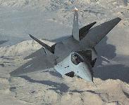

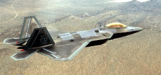
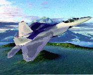


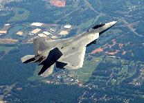


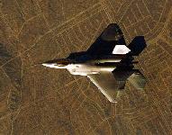
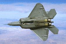

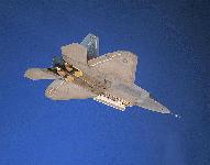
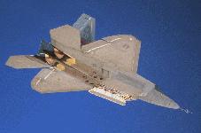
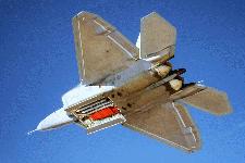

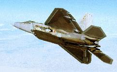
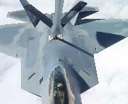
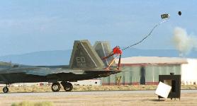
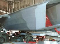


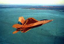

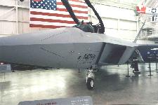

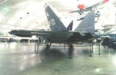
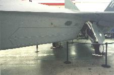


 or CC-BY-SA-3.0 (http://creativecommons.org/licenses/by-sa/3.0/)], via Wikimedia Commons")


 Image Courtesy of